Lab 4: Digital Audio
Hours spent on lab: 9 Hours
Hours procrastinated: \(e^\inf\) Hours
Overview
In this lab, we shift away from Hardware Description Language and our FPGA. We begin to make some set-up files for our Microcontroller STM32L432KCUx to access its internal clock, GPIO clocks, and Timer clocks to generate electrical pulses and delays in the form of square waves.
Hardware Setup
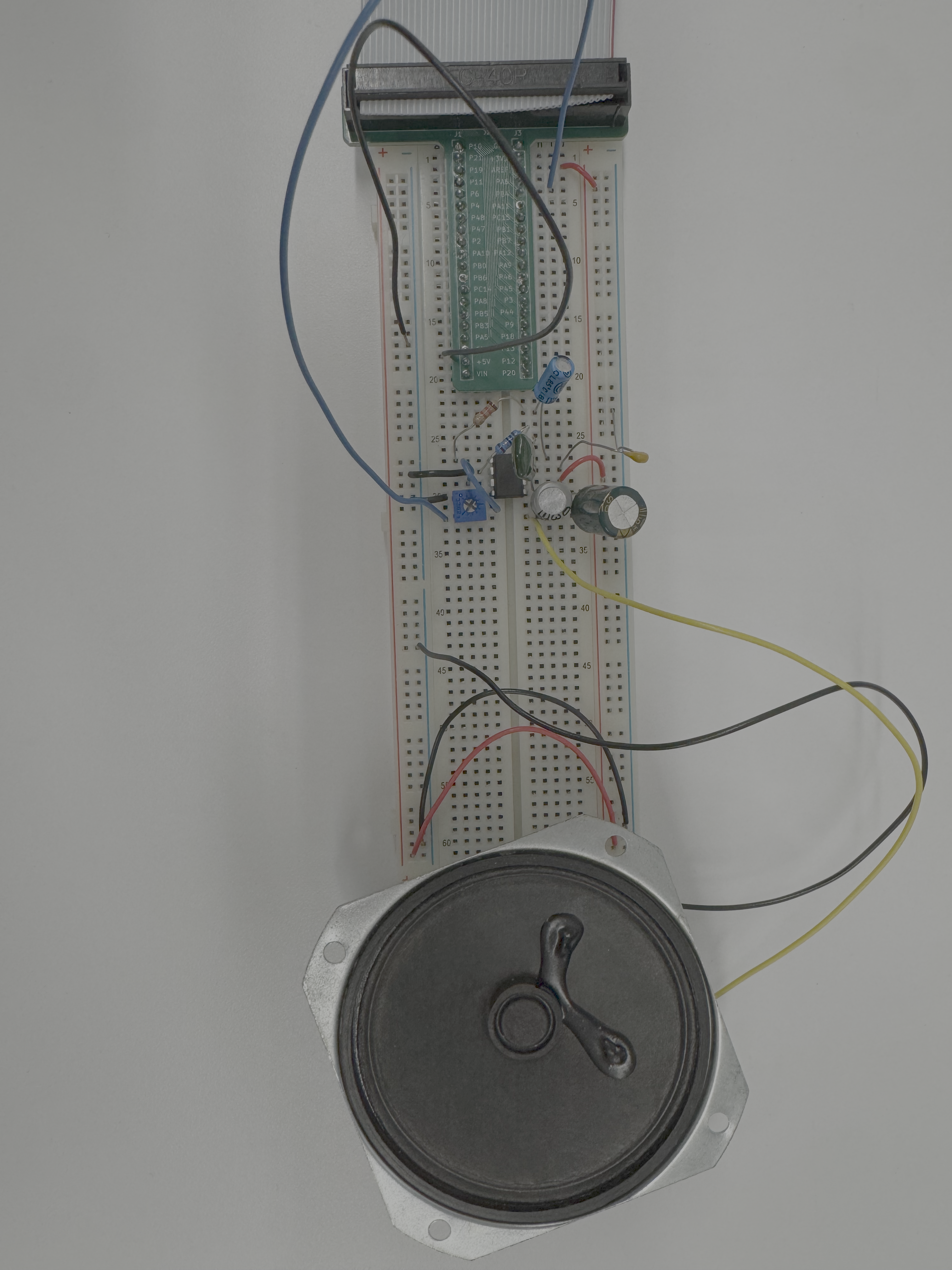
I followed figure 9-5 on the LM386 datasheet using the audio amplifier. To create my breadboard:
Schematic
The schematic for the circuit includes the MCU, Piano switches, Push-Buttons, and the LM386 Audio Amplifier.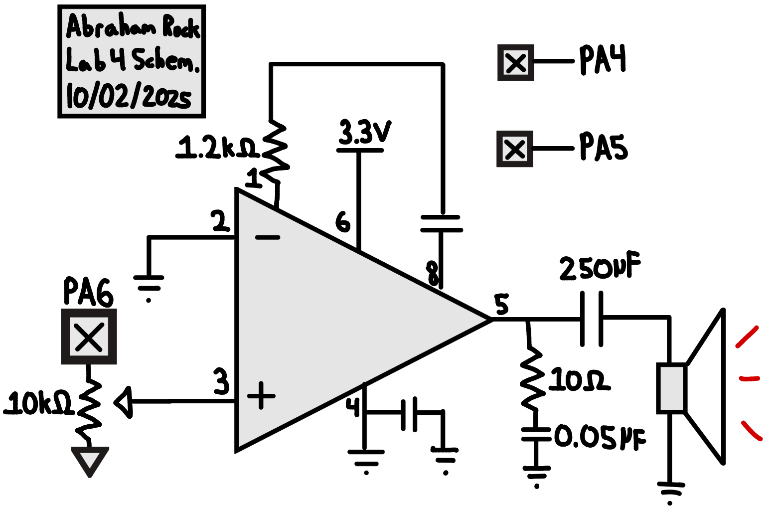
Calculations
Delay
Given the following formulas:
- \(f_{timer}=\frac{f_{clk}}{PSC+1}\)
- \(f_{reload}=\frac{f_{timer}}{ARR+1}\)
- \(T=\frac{PSC+1}{f_{clk}}\times (ARR+1)\)
Hardcoding PSC for delay as 2500, we can use our first equation \(f_{timer}=\frac{80 * 10^6 Hz}{2501} \approx 31987.2 Hz\). We can then use our 3rd equation to see our minimum and maximum delay depending on what \(ARR\) is set as as the incrementer.
Minimum (ARR = 1): \(T=\frac{2501}{80 * 10^6 Hz}\times (2) \approx 62.5 \mu s\).
Maximum (ARR = 65635 = 0xFFFF): \(T=\frac{2501}{80 * 10^6 Hz}\times (65535) \approx 2.05 s\).
Pulse Width Modulation
Given the following formula:
- \(f_{pwm}=\frac{f_{clk}}{(PSC+1)(ARR+1)}\)
Minimum (largest PSC and ARR): \(f_{pwm}=\frac{80 * 10^6 Hz}{65535^2} \approx 18.627 mHz\)
Maximum (smallest PSC and ARR): \(f_{pwm}=\frac{80 * 10^6 Hz}{2} = 40 MHz\)
So let’s go through some examples to see how accurate our production is even with the rounding and integer division taking place.
78 Hz (Eb2):
\(D = \frac{80*10^6}{78} \approx 1025641.03\).
So my code would choose a PSC Value of \(\frac{1025641.03}{65536} - 1 \approx 15.65 - 1\).
I use ceil to round numbers with a decimal of 0.5 or more to the next largest integer so we end up getting \(16 - 1 = 15\).
It would then calculate a ARR Value of \(\frac{1025641.03}{15 + 1} \approx 64102.56\).
I use round to bring down numbers with a decimal of less than 0.5 to the next smallest integer getting us \(64103\).
Then calculating \(f_{clk} = \frac{80*10^6 Hz}{PSC * ARR} = \frac{80*10^6 Hz}{16 * 64103} \approx 77.995\).
We have an error of \(\frac{77.995 - 78}{78} \approx -0.0064 \%\).
440 Hz (A4):
\(D = \frac{80*10^6}{440} \approx 181818.\overline{18}\).
So my code would choose a PSC Value of \(\frac{181818.\overline{18}}{65536} - 1 \approx 2.8 - 1\).
I use ceil to round numbers with a decimal of 0.5 or more to the next largest integer so we end up getting \(3 - 1 = 2\).
It would then calculate a ARR Value of \(\frac{181818.\overline{18}}{2 + 1} \approx 60606.06\).
I use round to bring down numbers with a decimal of less than 0.5 to the next smallest integer getting us \(60606\).
Then calculating \(f_{clk} = \frac{80*10^6 Hz}{PSC * ARR} = \frac{80*10^6 Hz}{181818} = 440.00044\).
We have an error of \(\frac{440.00044 - 440}{440} = 0.0001 \%\).
1568 Hz (G6):
\(D = \frac{80*10^6}{1568} \approx 51020.41\).
So my code would choose a PSC Value of \(\frac{51020.41}{65536} - 1 \approx 0.77 - 1\).
I use ceil to round numbers with a decimal of 0.5 or more to the next largest integer so we end up getting \(1 - 1 = 0\).
It would then calculate a ARR Value of \(\frac{51020.41}{0 + 1} \approx 51020.41\).
I use round to bring down numbers with a decimal of less than 0.5 to the next smallest integer getting us \(51020\).
Then calculating \(f_{clk} = \frac{80*10^6 Hz}{PSC * ARR} = \frac{80*10^6 Hz}{51021} \approx 1567.97\).
We have an error of \(\frac{1567.97 - 1568}{1568} \approx -0.0019 \%\).
Verification

Percent Error = \(\frac{497.22 - 500}{500} \approx 0.56 \%\)
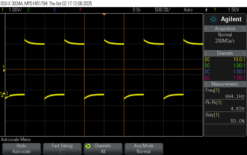
Percent Error = \(\frac{994.1 - 1000}{1000} \approx 0.59 \%\)

Percent Error = \(\frac{4973.7 - 5000}{5000} \approx 0.53 \%\)
AI Prototype
This week I prompted Claude AI with “What timers should I use on the STM32L432KC to generate frequencies ranging from 220Hz to 1kHz? What’s the best choice of timer if I want to easily connect it to a GPIO pin? What formulae are relevant, and what registers need to be set to configure them properly?”. For additional context, I was able to upload the Datasheet and Reference Manual to the AI so it could potentially go through and not hallucinate registers.
Claude AI Response Summary
Recommended Timer: TIM2 (32-bit general-purpose timer)
- Best for 220Hz-1kHz range due to 32-bit counter flexibility
- 4 channels available for PWM output
- Easy GPIO mapping via alternate functions
Key Formula:
f_output = f_timer / ((PSC + 1) × (ARR + 1))Where f_timer is typically 80 MHz, PSC is the prescaler value, and ARR is the auto-reload value.
Essential Registers:
-
TIMx_PSC- Prescaler (divides clock) -
TIMx_ARR- Auto-reload register (defines period) -
TIMx_CCRx- Capture/compare (sets duty cycle) -
TIMx_CCMR- Set to PWM mode (OCxM = 110 or 111) -
TIMx_CCER- Enable channel output -
TIMx_CR1- Enable counter
Example (440Hz): With 80 MHz clock, PSC=79, ARR=2272 gives 440.05 Hz
GPIO Connection: Configure pin alternate function per datasheet tables (e.g., PA0 = TIM2_CH1 with AF1)
I think it did a good job with this response. From my understanding of the reference manual, TIM2 is one of the more robust timers on our microcontroller and could definetley be used to produce a PWM signal.
Conclusion
The design worked as intended. You are able to trigger the given song: Fur Elise by the press of a button, and trigger my song of choice: Un Sospiro by clicking a switch.