Lab 6: The Internet of Things and Serial Peripheral Interface Learning
Hours spent on lab: 15 Hours
Overview
In this lab, we learn about one of the most used methods of data communication, Serial Peripheral Interface or SPI. This saves people from making cumbersome circuits and avoid wiring many different signals in parallel. For learning this, we are using the DS1722 Temperature Sensor which communicates some hex value based on the temperature which you can translate to some threshold to find temperature in known units.
Hardware Setup
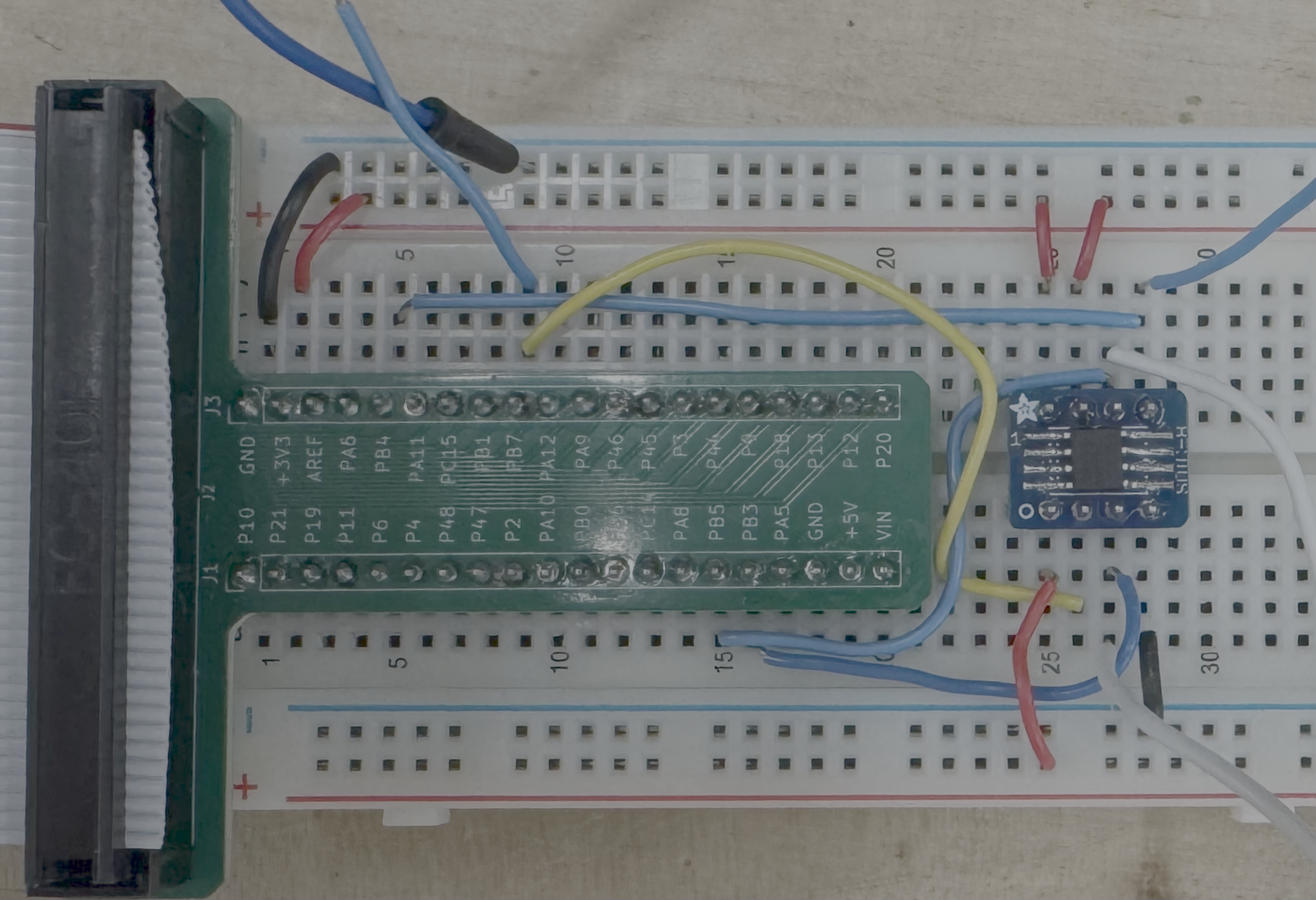
We were provided with a breakout board to easily access the necessary Power and SPI pins. I connected the \(\text{COPI}\), \(\text{CIPO}\), \(\text{S}_{\text{CLK}}\), and \(\text{CS}\) pins respectively from our MCU’s development board to our Temperature Sensor.
Schematic
The schematic for the circuit includes the MCU, and the DS1722 Temperature Sensor.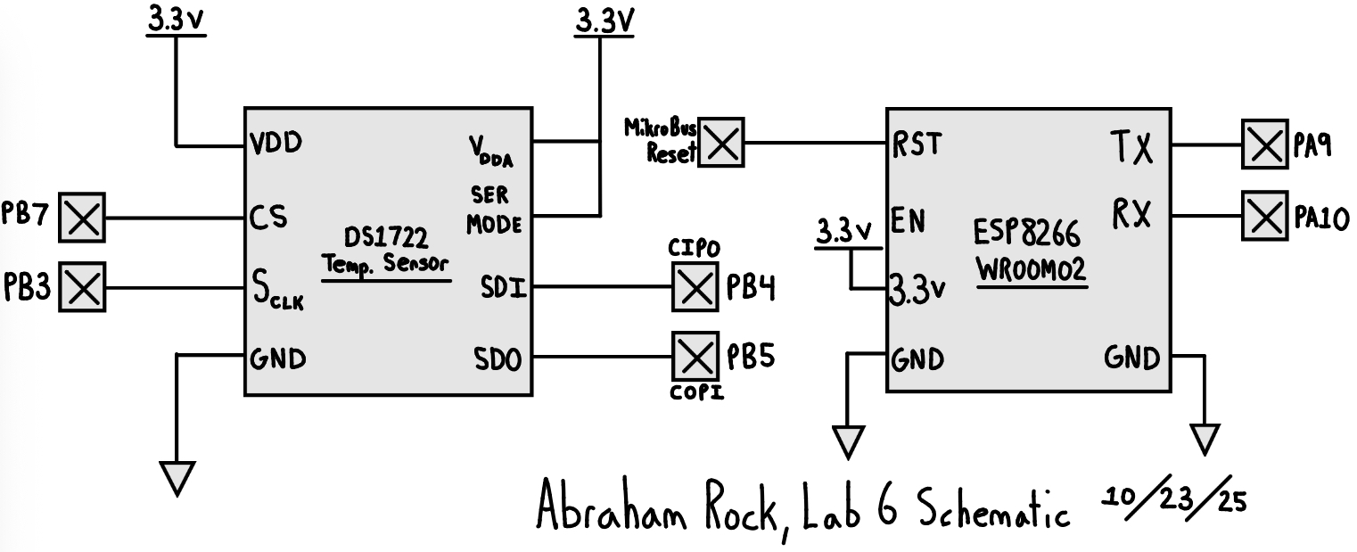
Calculations
The method of reading temperature through SPI is \(\text{Temperature} [\degree \text{C}] = \text{MSB} + \frac{\text{LSB}}{256}\). Which we can retrieve by shifting the 8-bit word by 8 to get the most significant bit.
| Resolution (bits) | Command Byte | Conversion Time (ms) |
|---|---|---|
| 8 | 0xE0 | 75 |
| 9 | 0xE2 | 150 |
| 10 | 0xE4 | 300 |
| 11 | 0xE6 | 600 |
| 12 (default) | 0xE8 | 1200 |
Verification
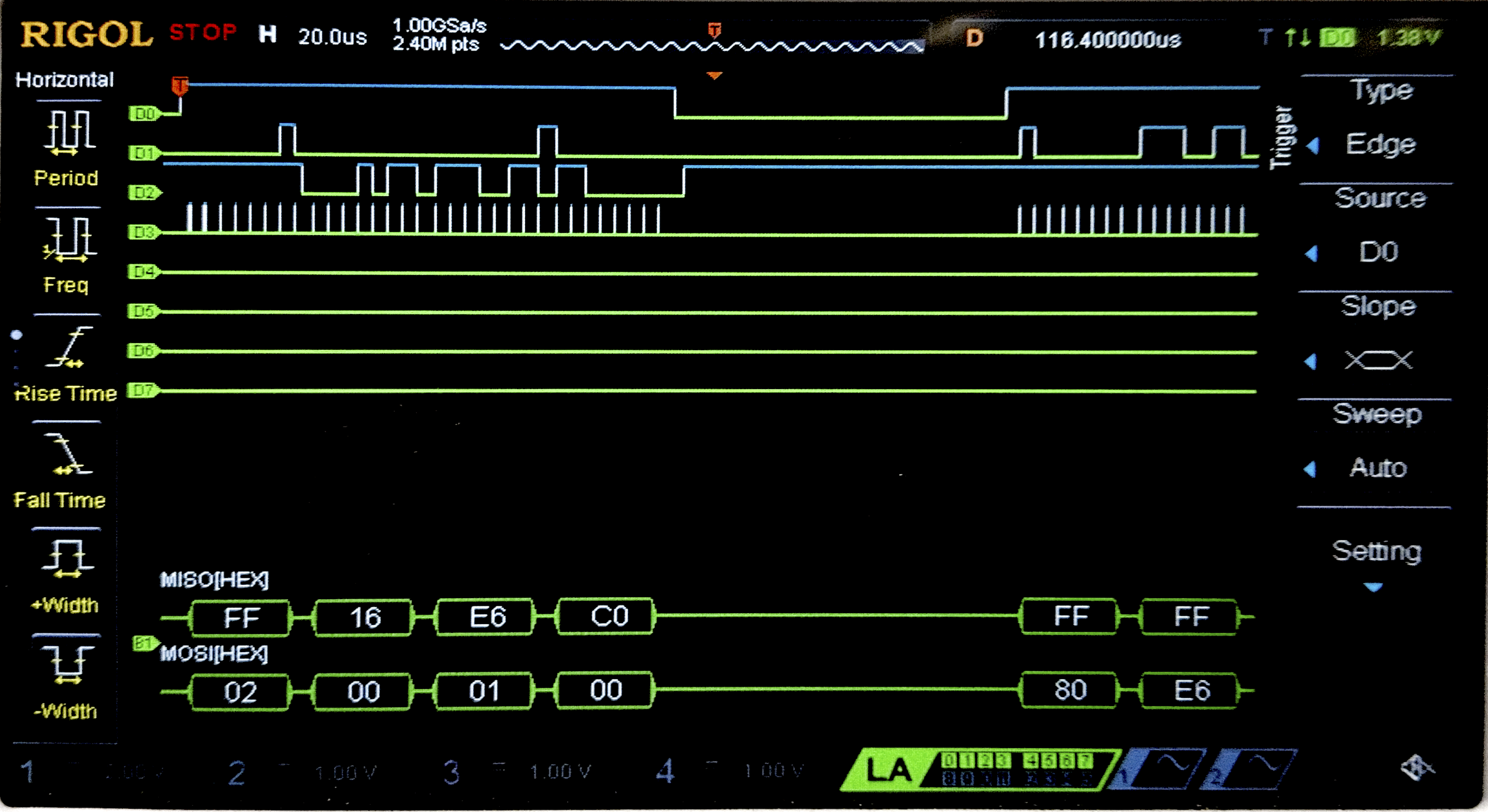
Connecting the SPI data pins to the oscilloscope logic analyzer and running a SPI function like our temperature read function, we can visualize the command signals, dummy bits, and SPI output (LSB and MSB) on the oscilloscope.
AI Prototype
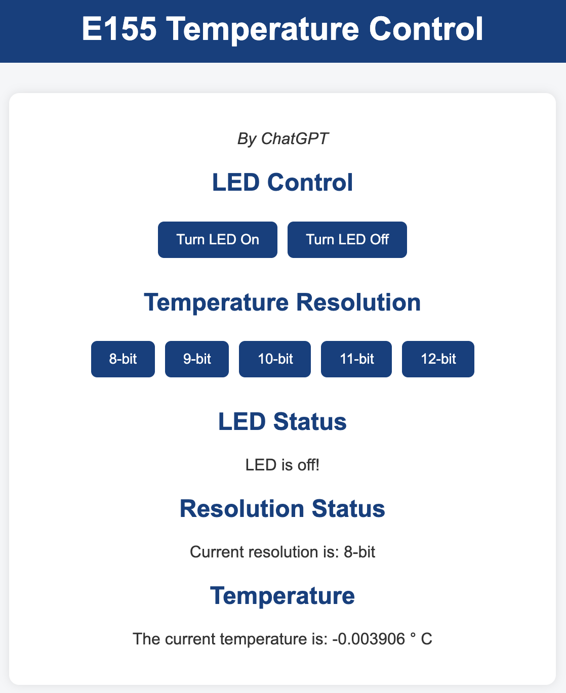
This week I prompted ChatGPT with “I’m making a web portal to interface with a temperature sensor. Create a HTML page that looks good and is intuitive to show the temperature, control an LED, and change the precision of the readout.” For additional context, I provided the macros I was using for pin outs.
#include "stm32l432xx.h"
#include stdint.h

#define DS1722_CS_LOW()    (GPIOA->BSRR = (1U << (SPI_CS + 16))) // Clear bit
#define DS1722_CS_HIGH()   (GPIOA->BSRR = (1U << SPI_CS))        // Set bit

#define DS1722_READ_CMD    0x02  // Read temperature MSB register
#define DS1722_TEMP_MSB    0x02  // Address of temperature MSB register

float read_temp_DS1722(void)
{
    uint8_t msb, lsb;
    uint16_t raw_temp;

    // Select DS1722
    DS1722_CS_LOW();

    // Send address of temperature MSB (auto-increment allows reading both bytes)
    while (!(SPI1->SR & SPI_SR_TXE));
    *((__IO uint8_t *)&SPI1->DR) = DS1722_TEMP_MSB;
    while (!(SPI1->SR & SPI_SR_RXNE));
    (void)SPI1->DR; // dummy read to clear RXNE

    // Read MSB
    while (!(SPI1->SR & SPI_SR_TXE));
    *((__IO uint8_t *)&SPI1->DR) = 0x00;  // dummy byte
    while (!(SPI1->SR & SPI_SR_RXNE));
    msb = SPI1->DR;

    // Read LSB
    while (!(SPI1->SR & SPI_SR_TXE));
    *((__IO uint8_t *)&SPI1->DR) = 0x00;
    while (!(SPI1->SR & SPI_SR_RXNE));
    lsb = SPI1->DR;

    // Deassert CS
    DS1722_CS_HIGH();

    // Combine and convert
    raw_temp = ((uint16_t)msb << 8) | lsb;
    float temp_c = (float)raw_temp / 256.0f; // 1 LSB = 1/256 °C

    return temp_c;
}
I think the AI did really good this week. Its design looks like some cheap web app that I’d see which is sort of nice and well within specification.
For the actual reading temperature SPI code, I was very impressed, SPI has a lot of configuration options that I definetly struggled the most with and assumed the LLM would hallucinate registers or settings making it not work.
Substiting both the web page and SPI reading function didn’t make any functionality changes to my project making it work just as intended.
Conclusion
The design worked as intended. The temperature can go seamlessly into the negative range and reads what seems like reasonable values. A user can select a reading resolution through the webpage.