Lab 7: The Advanced Encryption Standard
Hours spent on lab: 12 Hours
Overview
After learning SPI Communication in Lab 6, we are returning back to System Verilog and our FPGA to incorporate our new learned skill to have them communicate. Our Microcontroller will act as the host, sending a 128-bit plaintext message and a 128-bit key via SPI. Our FPGA performs a very complex sequence of operations to function as a 128-bit AES encryption hardware accelerator. The FPGA receives the inputs, computes the encryption, and transmits the resulting ciphertext back to the microcontroller for verification.
Block Diagram
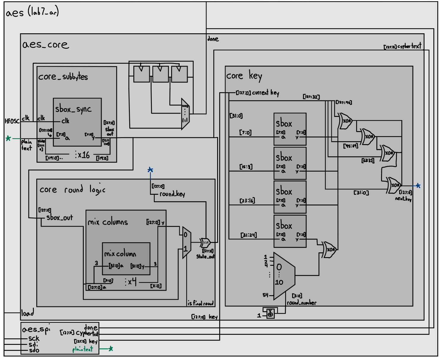
The block diagram for the hardware involves a top-level module (aes_starter) which instantiates the provided SPI interface and the custom aes_core module.
Due to synthesis constraints, the logic is too large to implement all encryption rounds as one giant block of combinational logic. Therefore, the aes_core must be designed to perform the rounds sequentially. This architecture is partitioned into a datapath and a controller.
Controller: A Finite State Machine (FSM) that generates the control signals to manage the flow of data through the datapath. It sequences the 10 rounds of encryption, asserts the correct multiplexer select signals, and manages register enables. The FSM must account for the one-cycle latency of the sbox synchronous RAM lookup.
Datapath: Consists of registers to hold the 128-bit intermediate state and the round key. It includes multiplexers and the combinational logic blocks for the four main AES transformations:
- sbox: The provided byte-substitution module (using sbox.txt).
- ShiftRows: A combinational wire-shuffling module.
- MixColumns: The provided Galois field arithmetic module.
- AddRoundKey: A bitwise XOR operation.
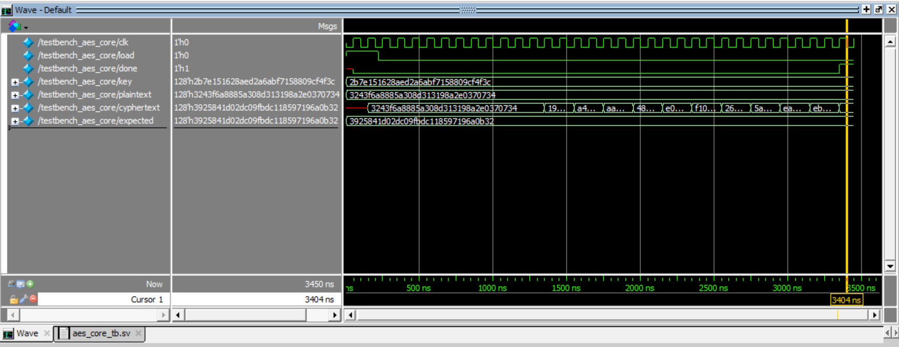
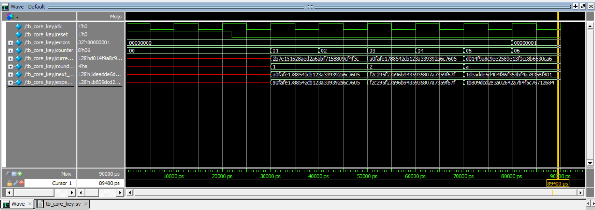
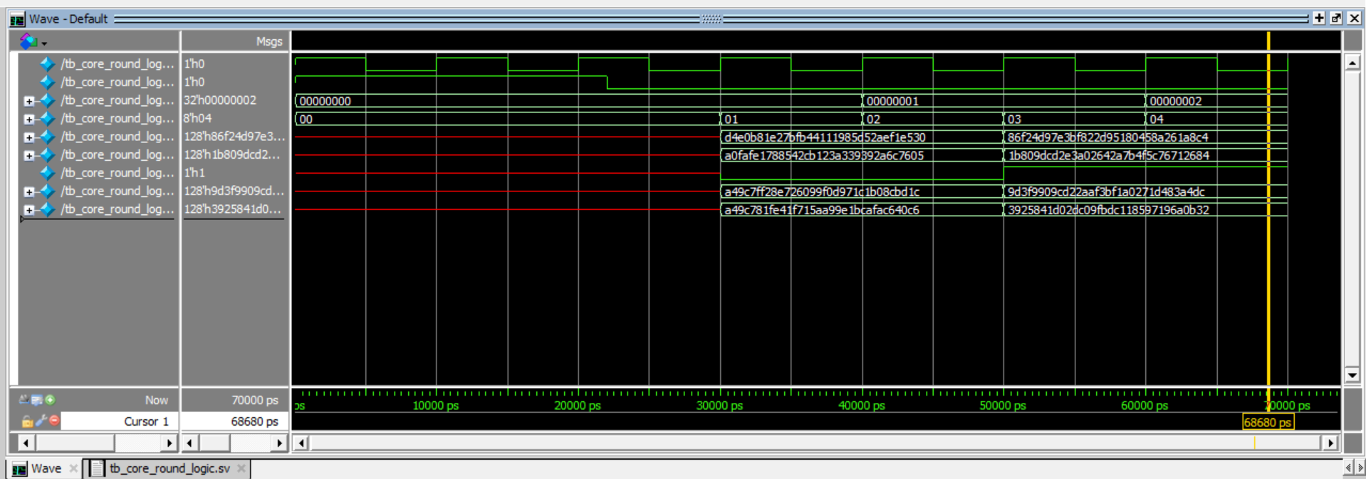
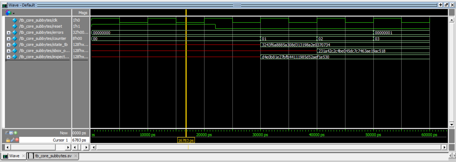
Simulation Verification
For my 4 custom modules to implement AES Encryption, you can see my verification of each of them: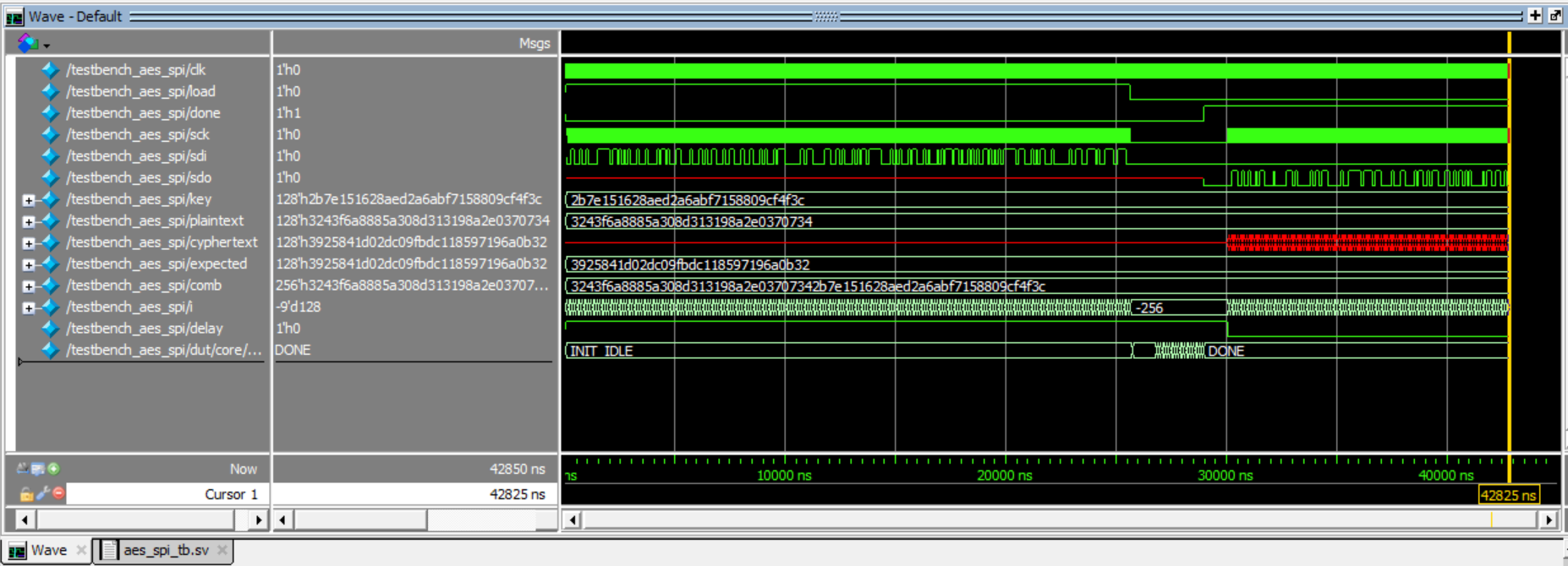
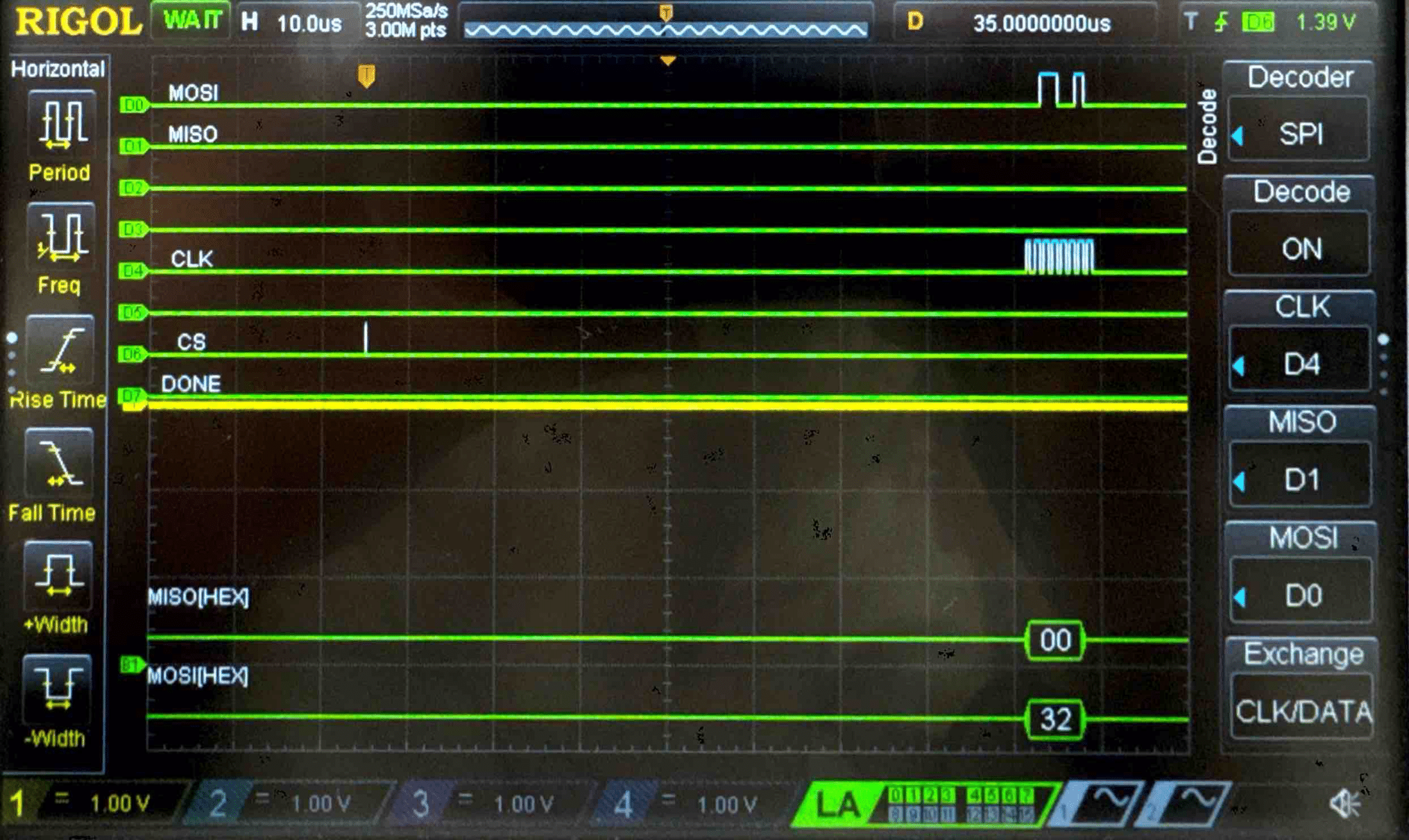
Hardware Verification
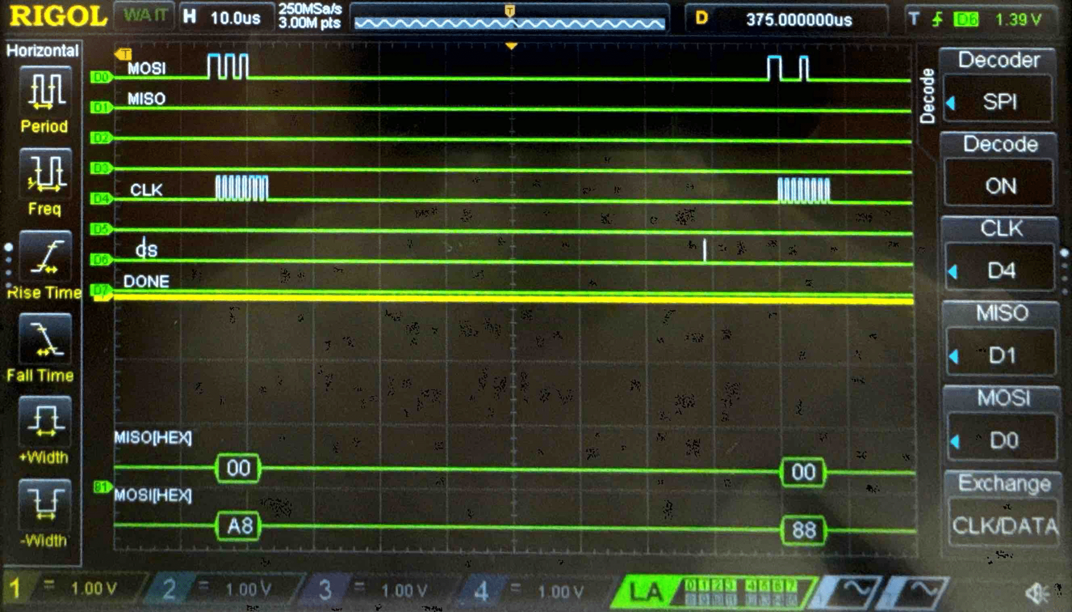
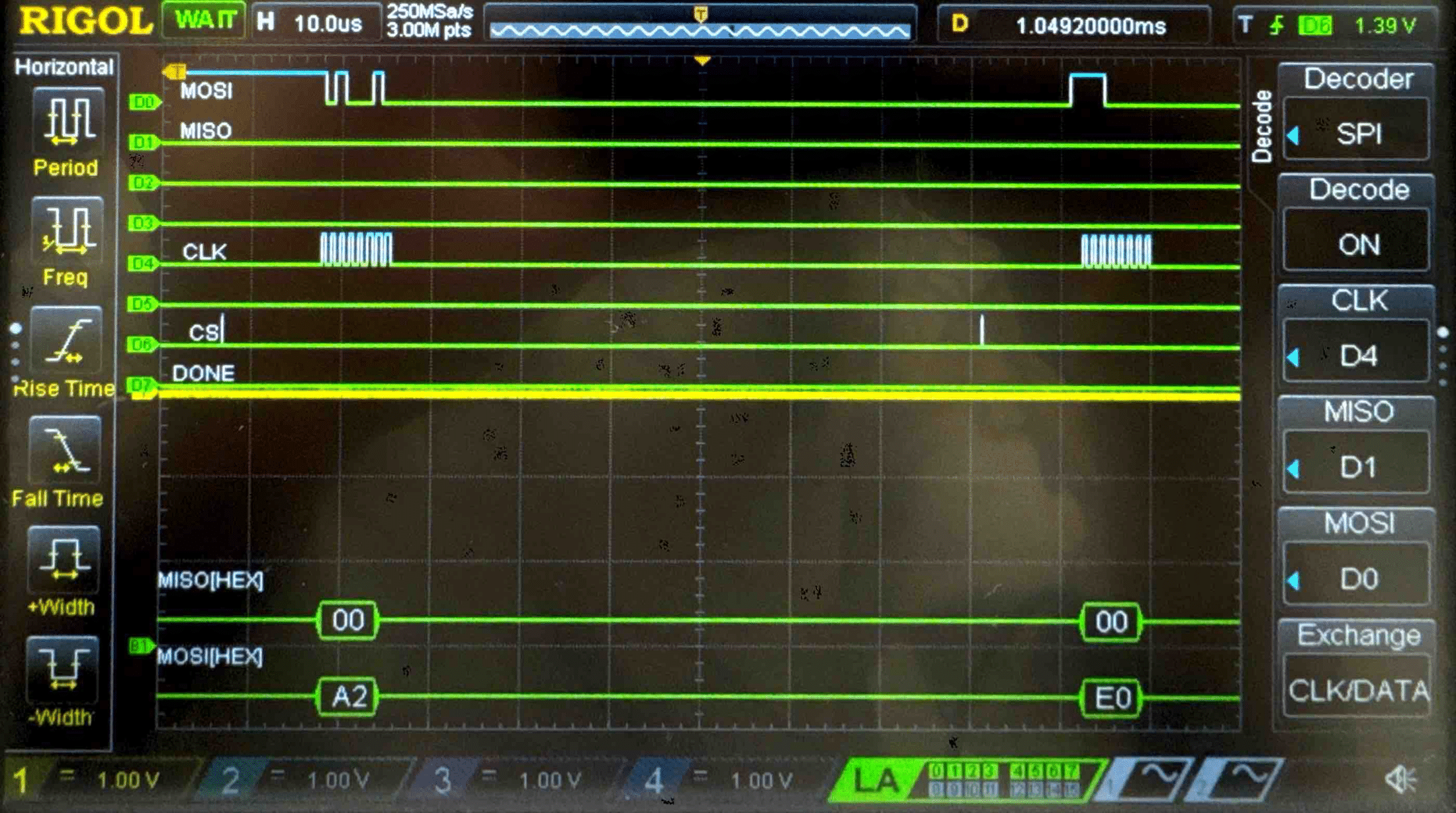
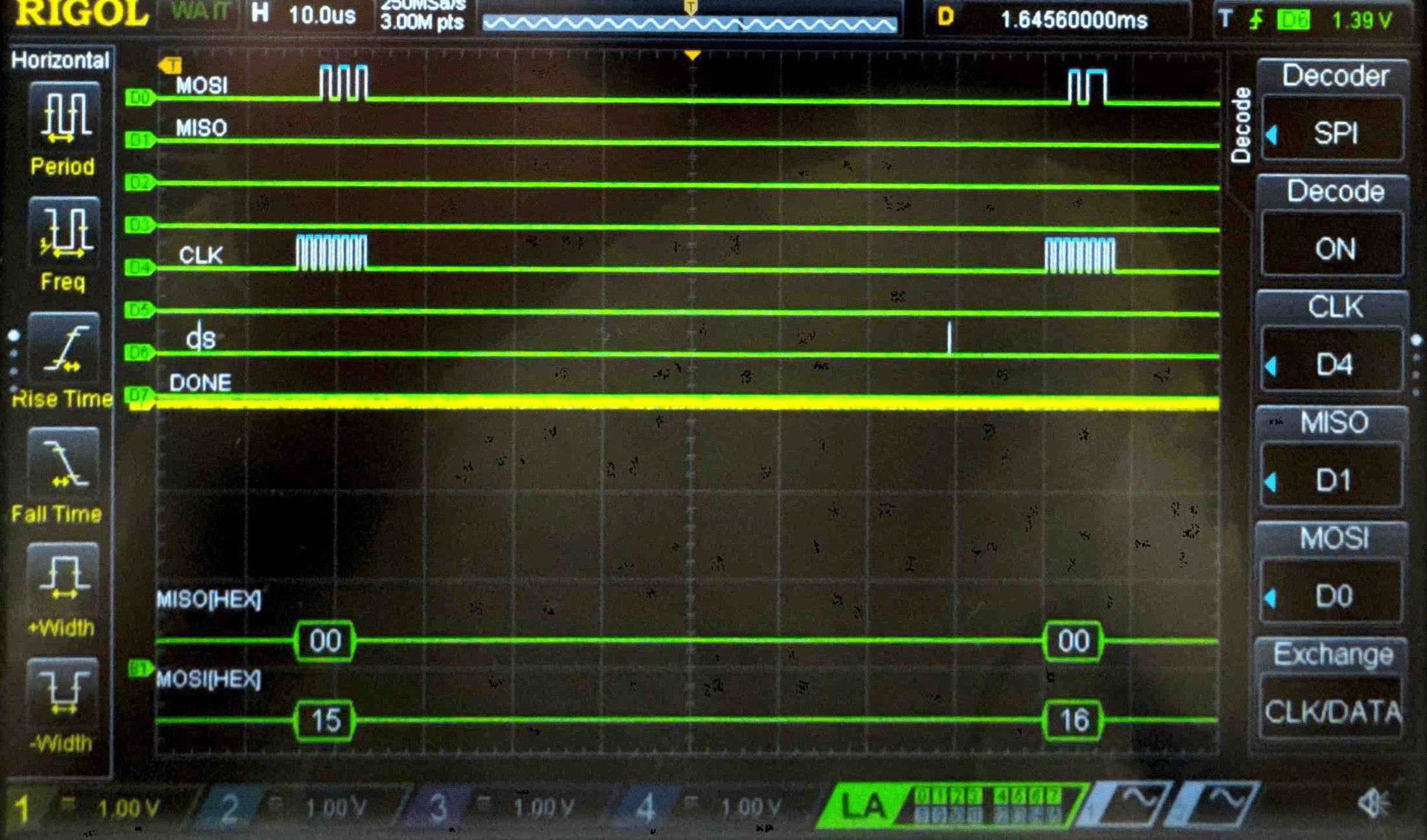
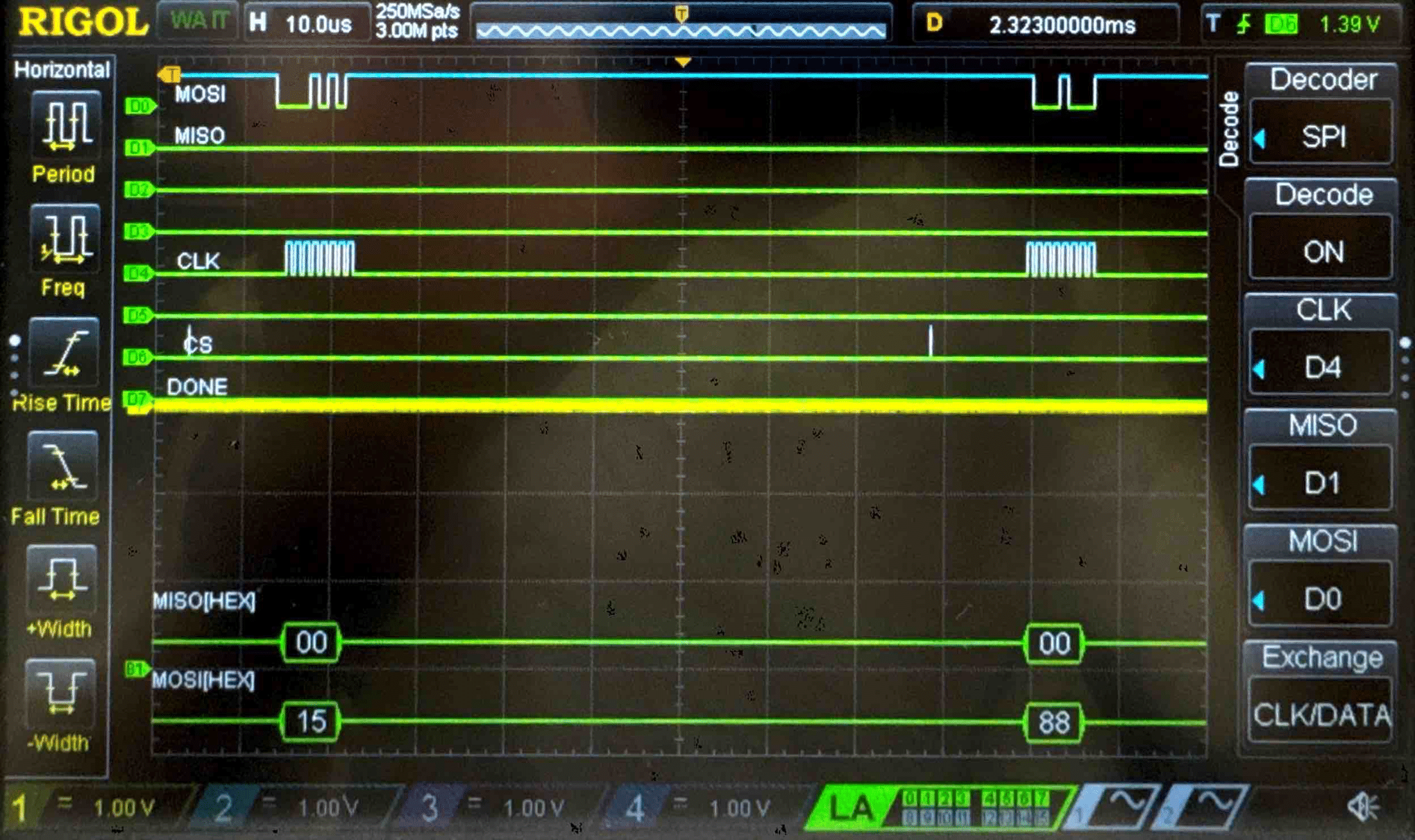
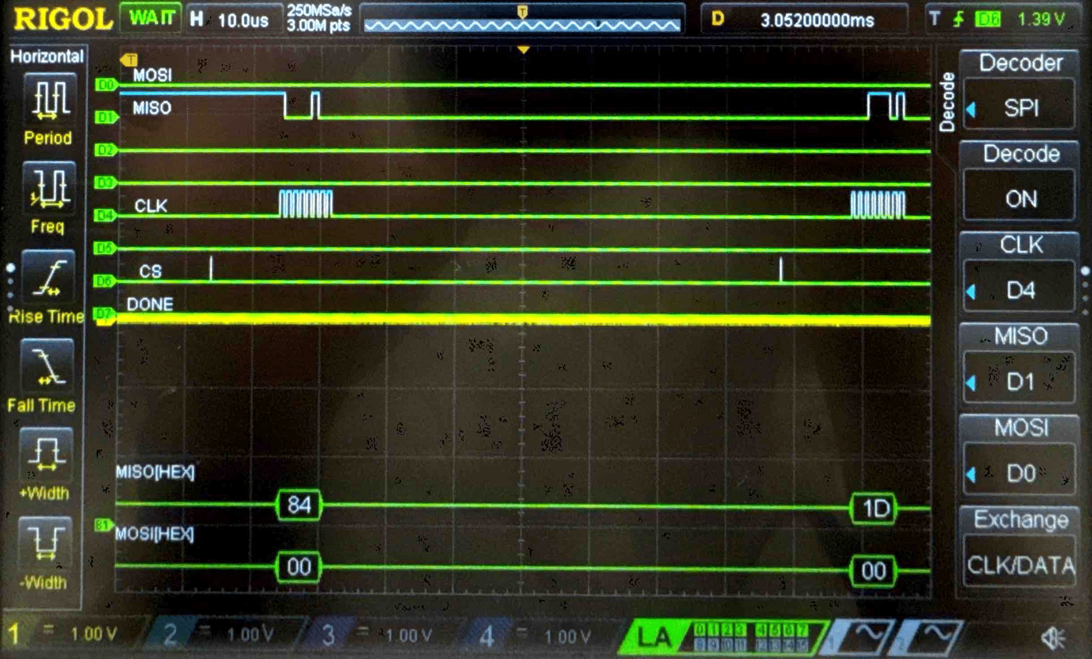
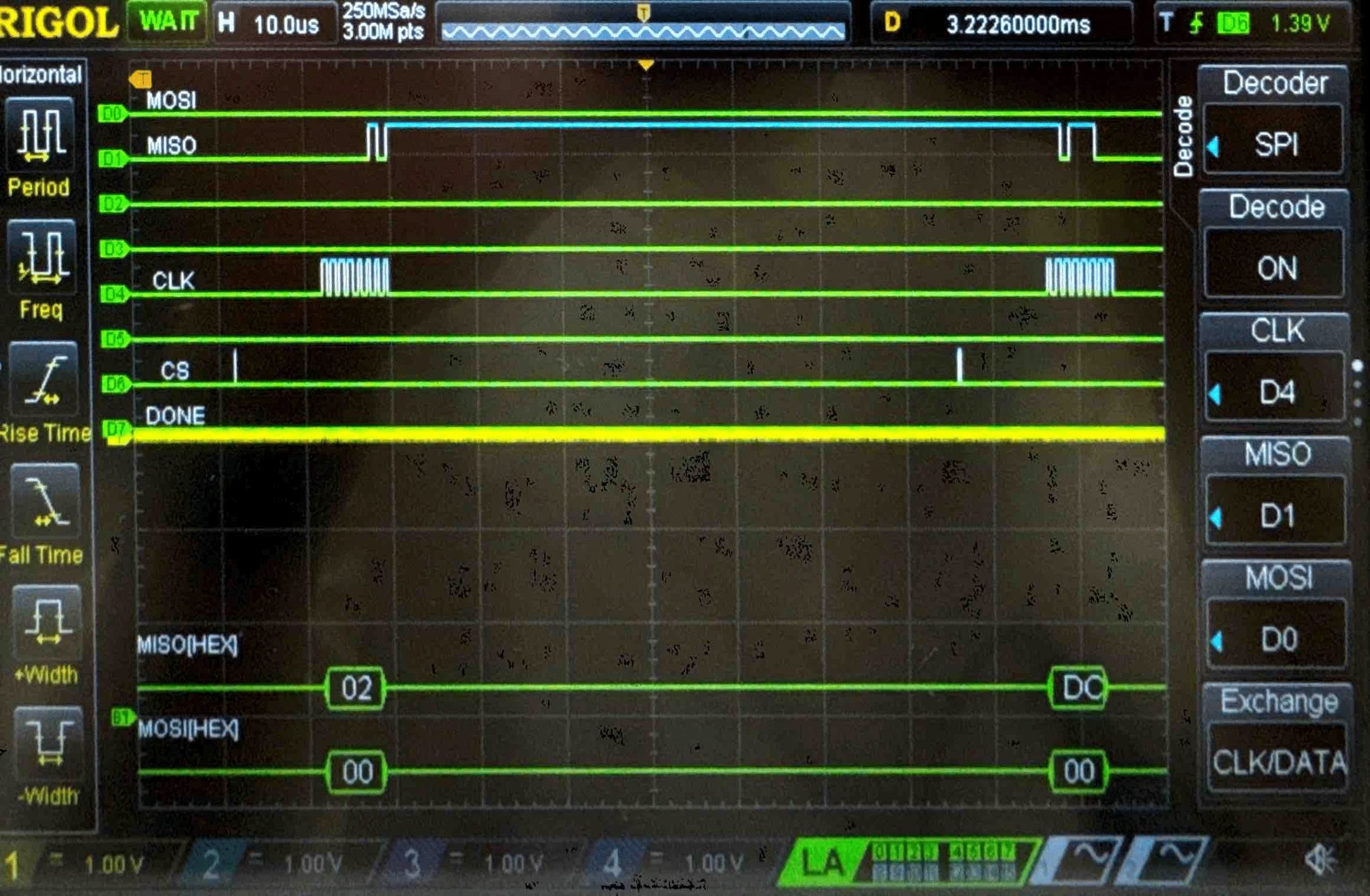
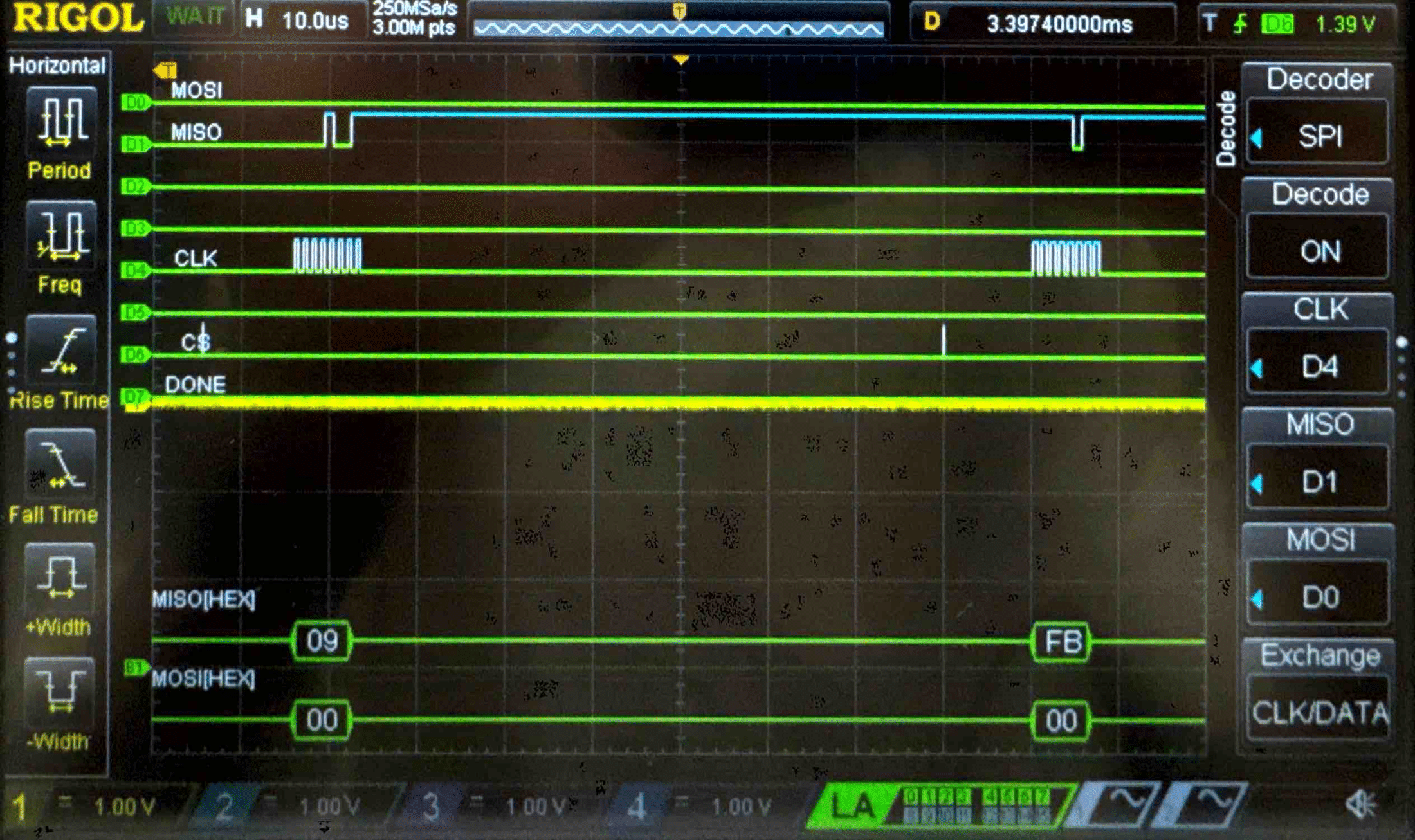
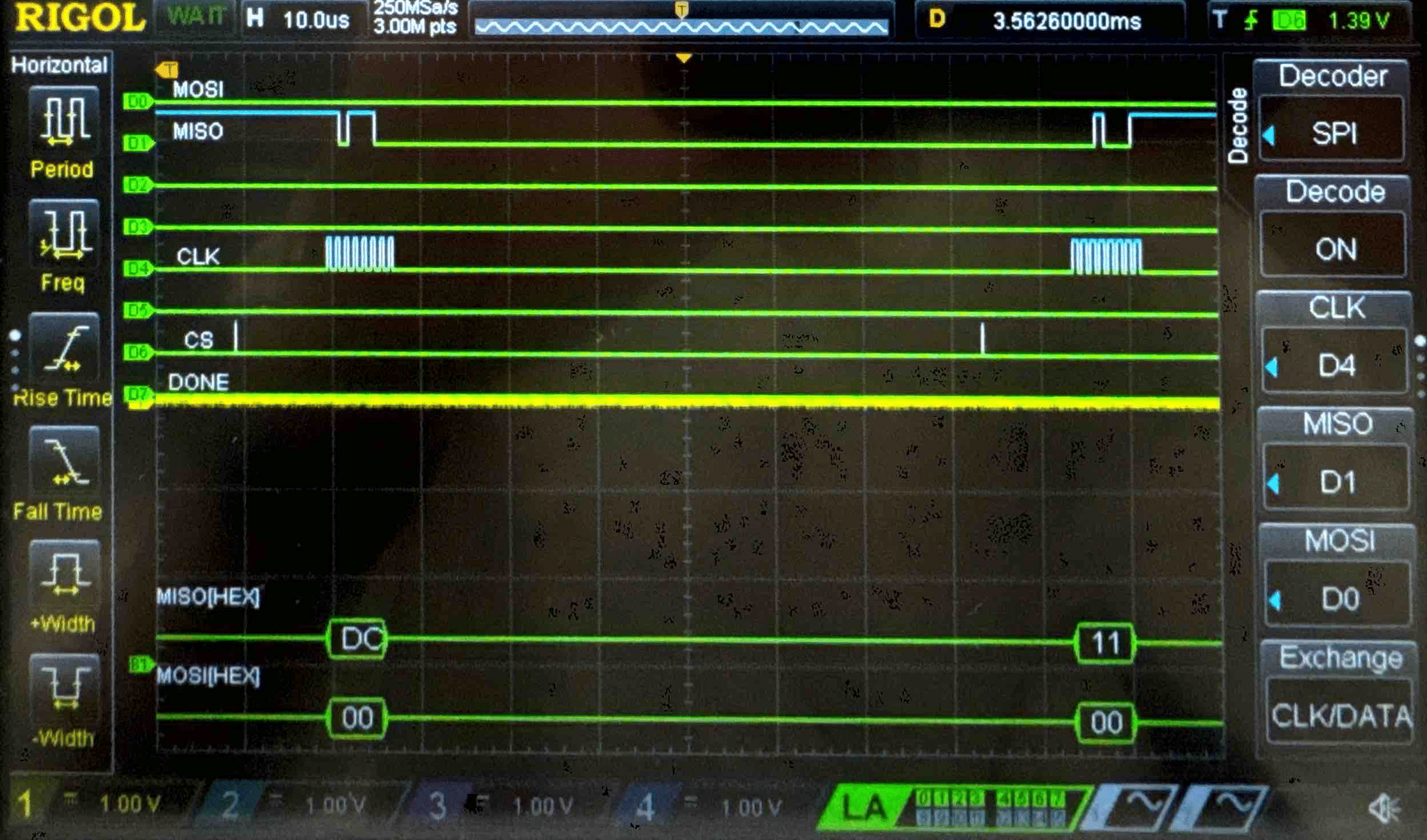
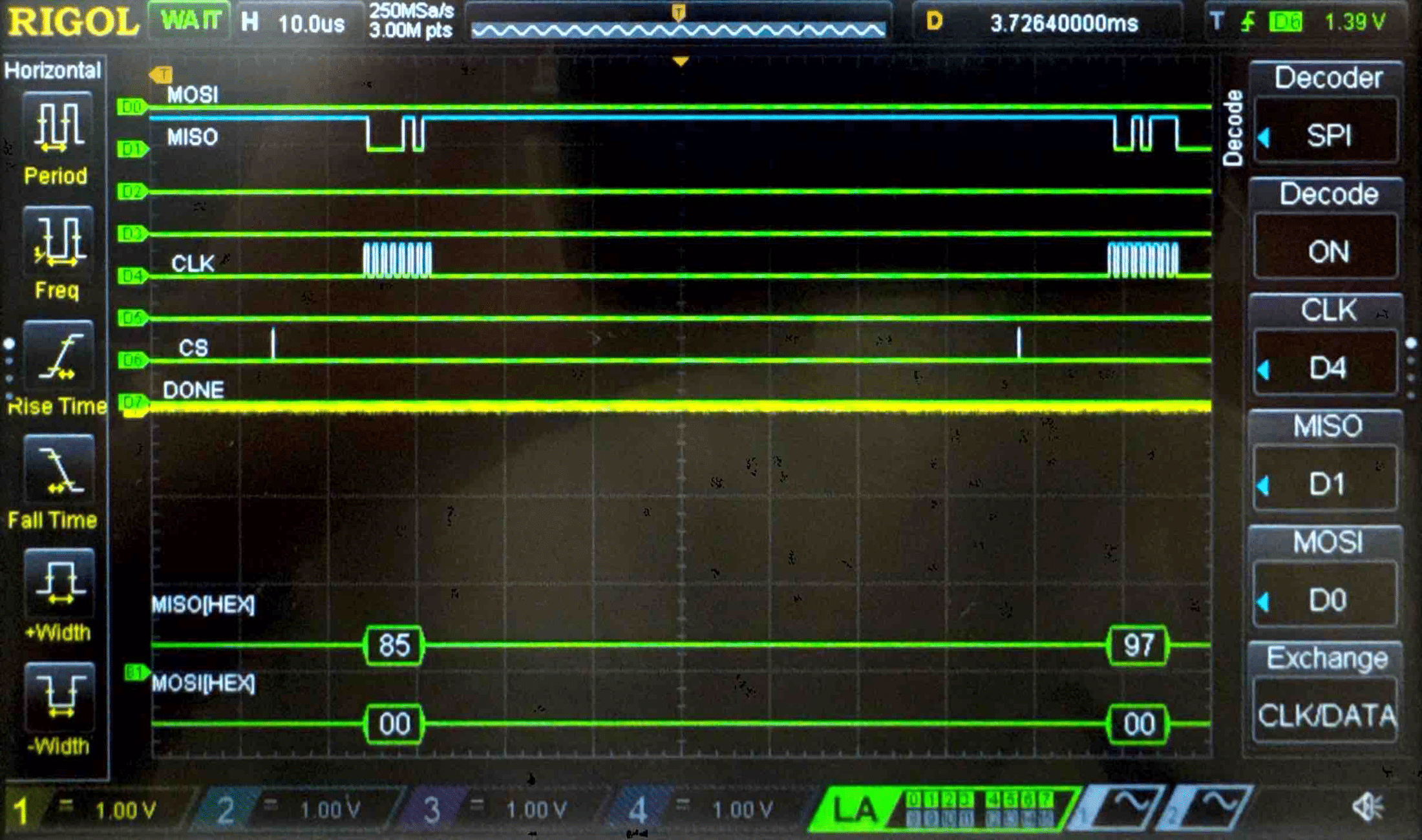
Connecting the SPI data pins to the oscilloscope logic analyzer and running a SPI function like our temperature read function, we can visualize the command signals, SPI output, and encrypted words being sent to and from the FPGA.
Plain Text - Logic Analyzer Trace
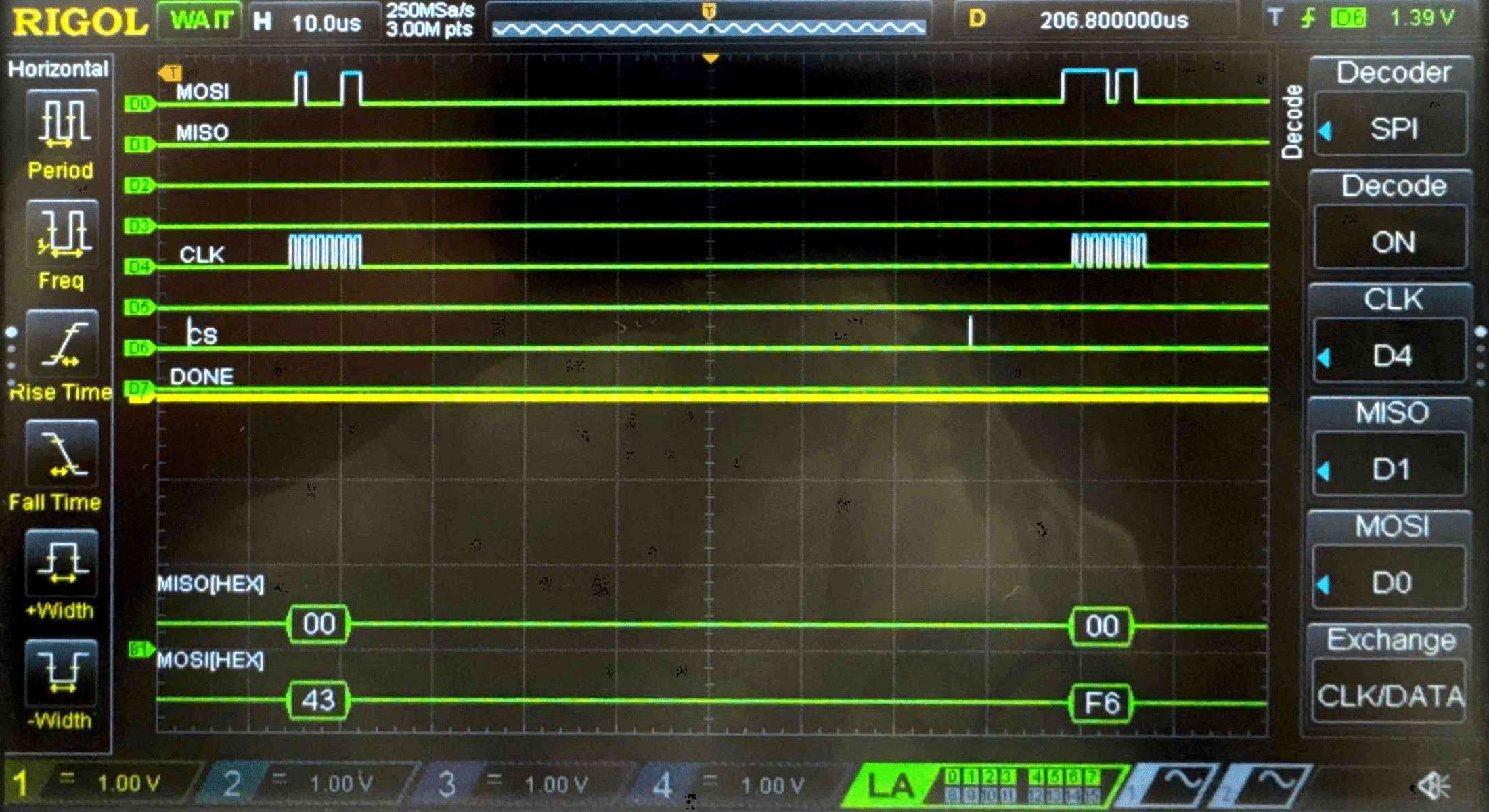
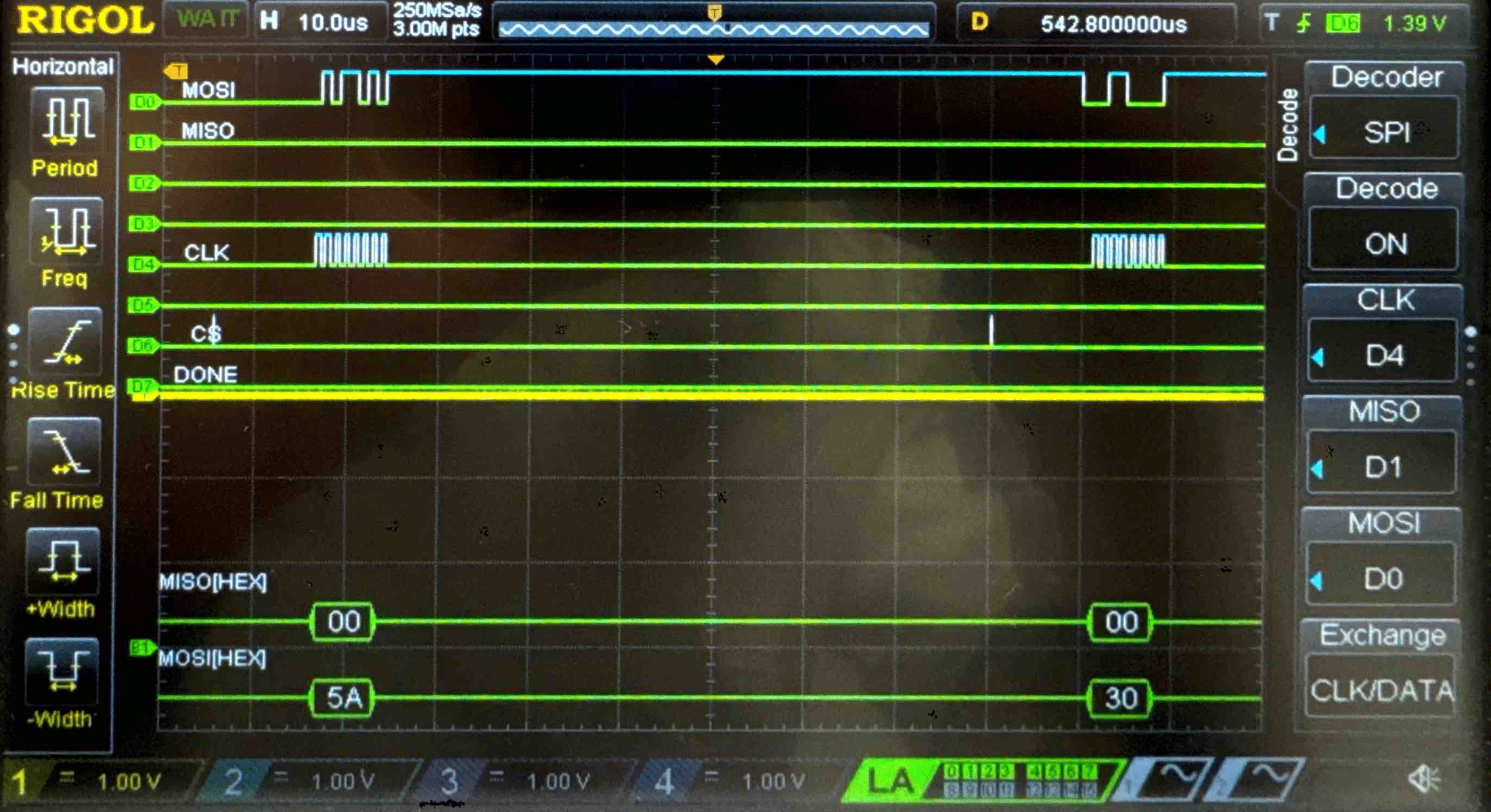
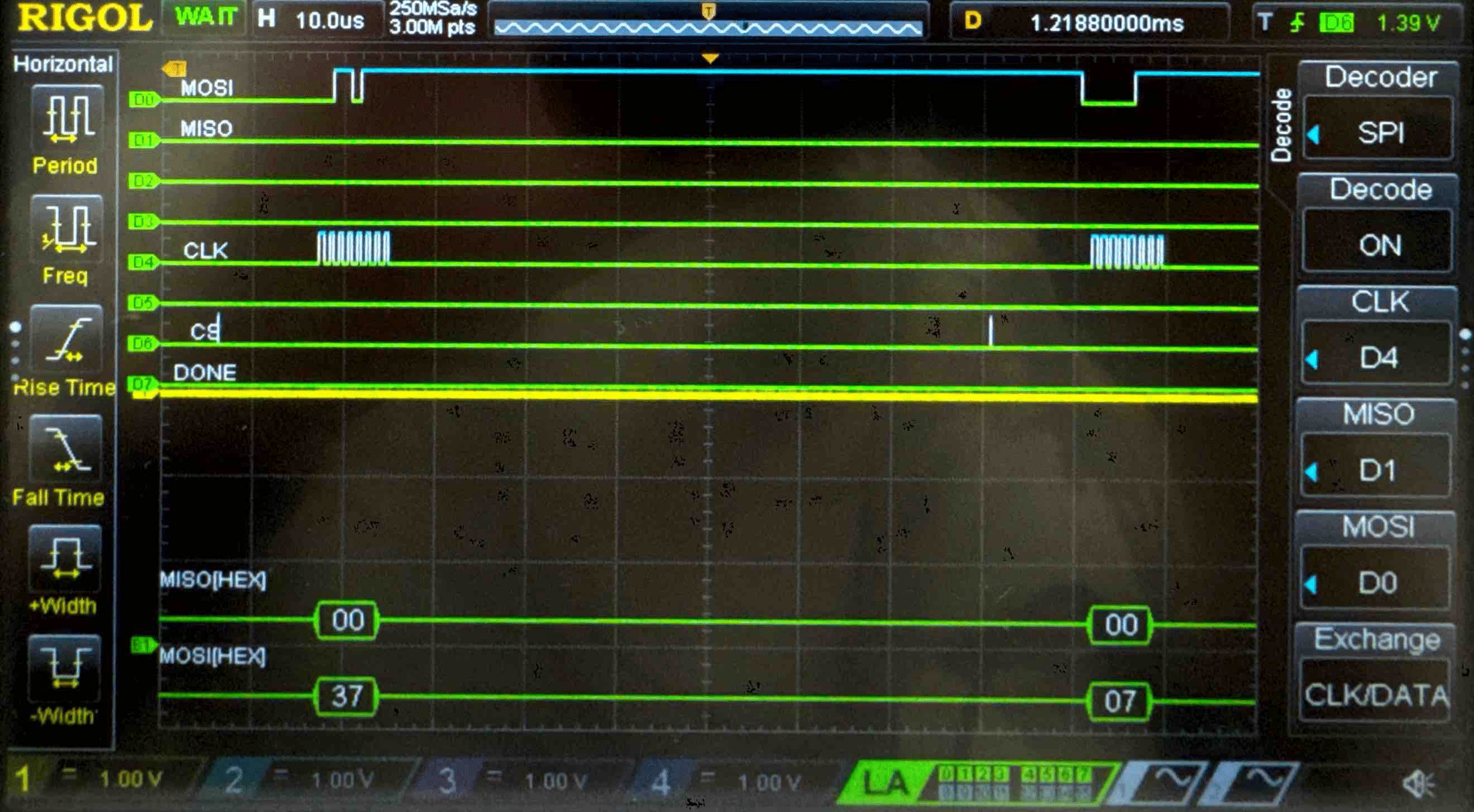
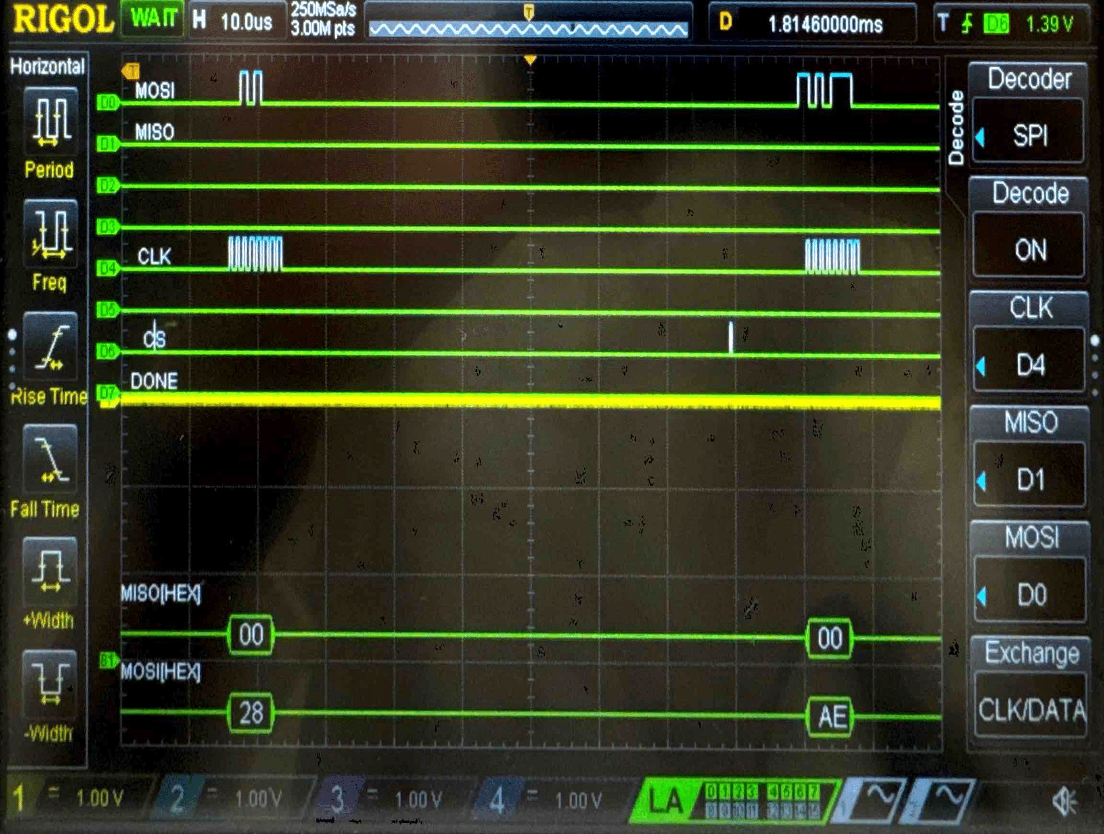
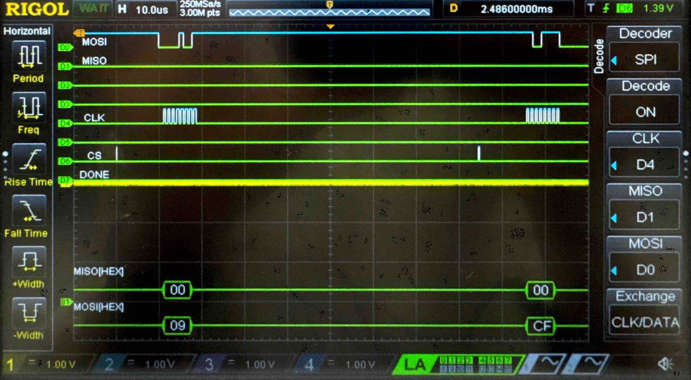
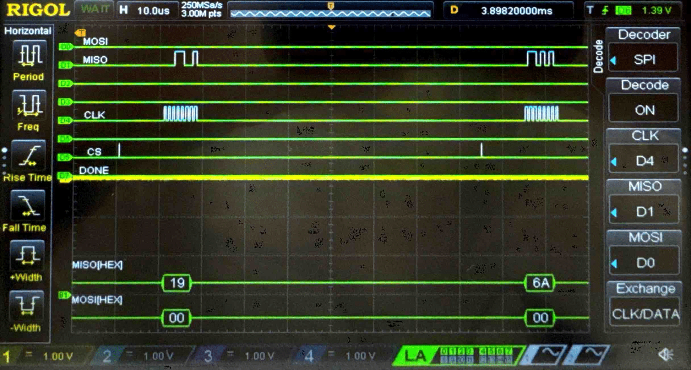
Key - Logic Analyzer Trace
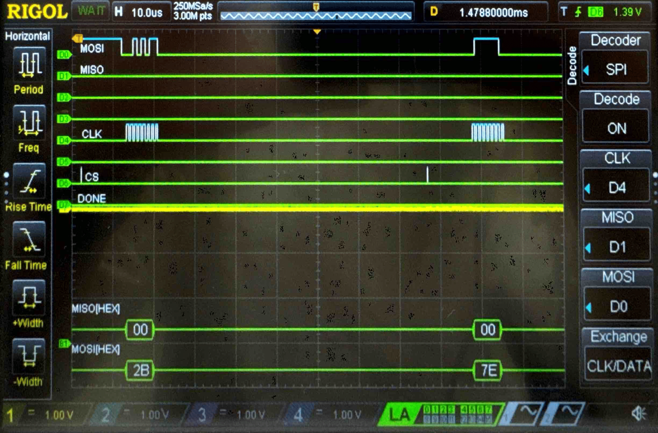
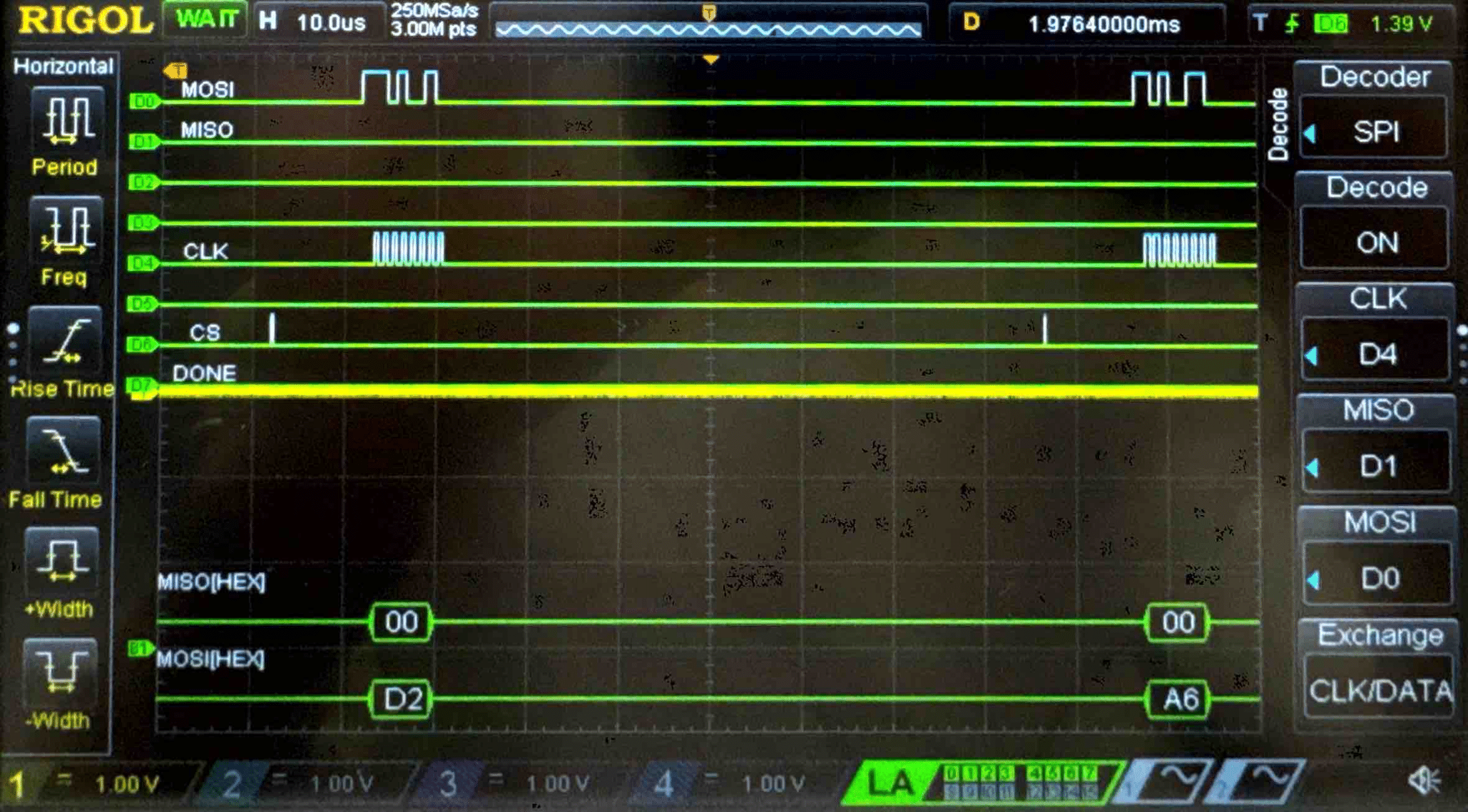
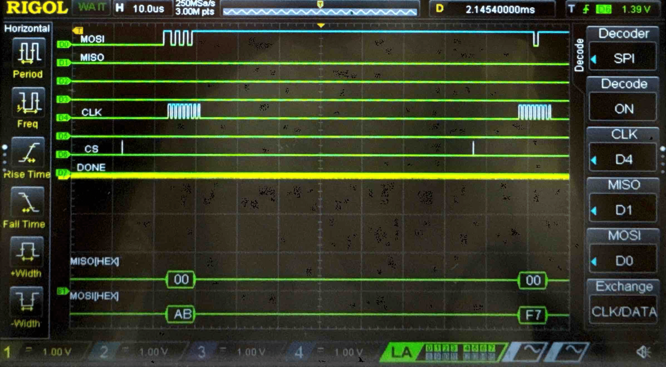
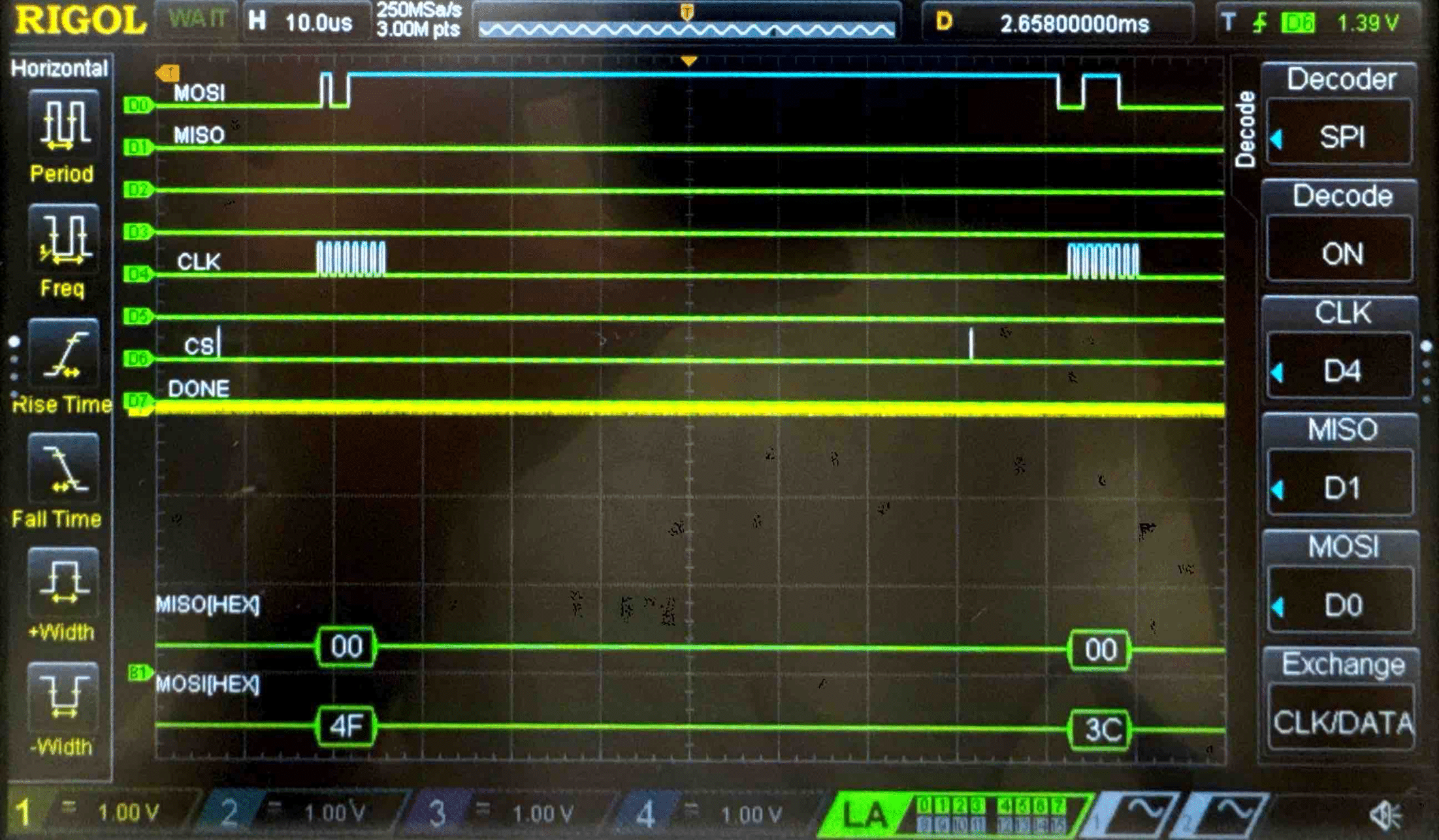
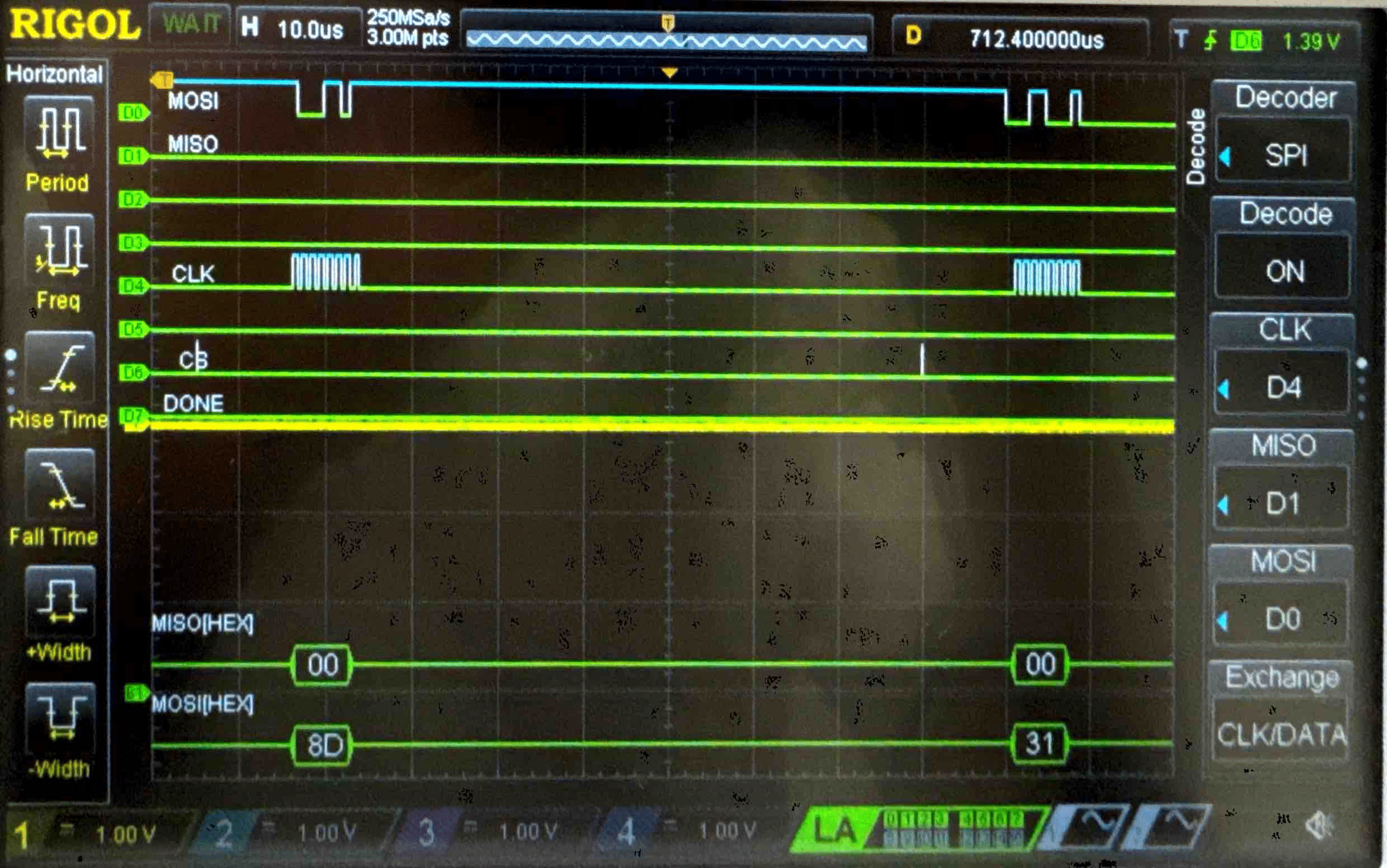
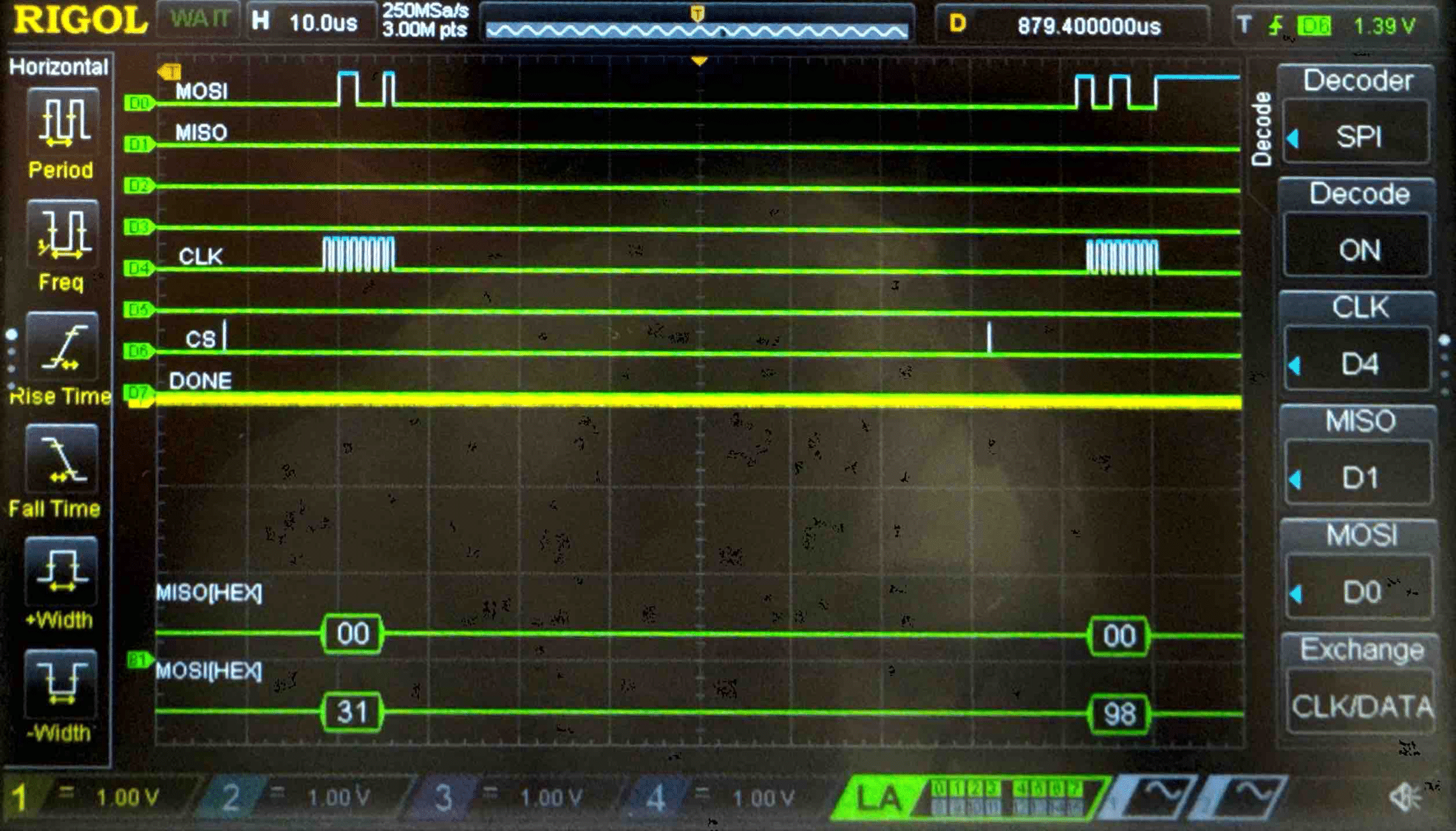
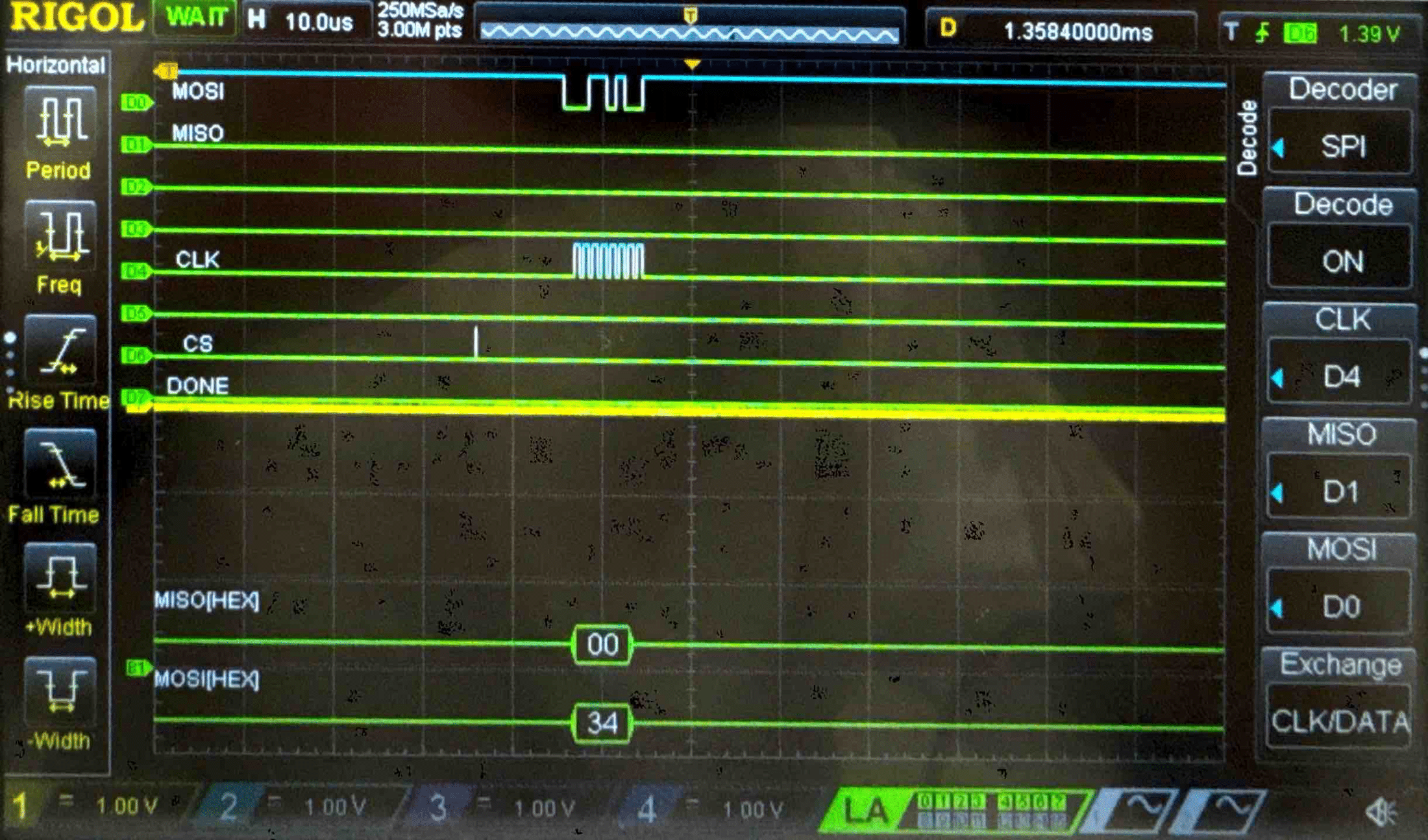
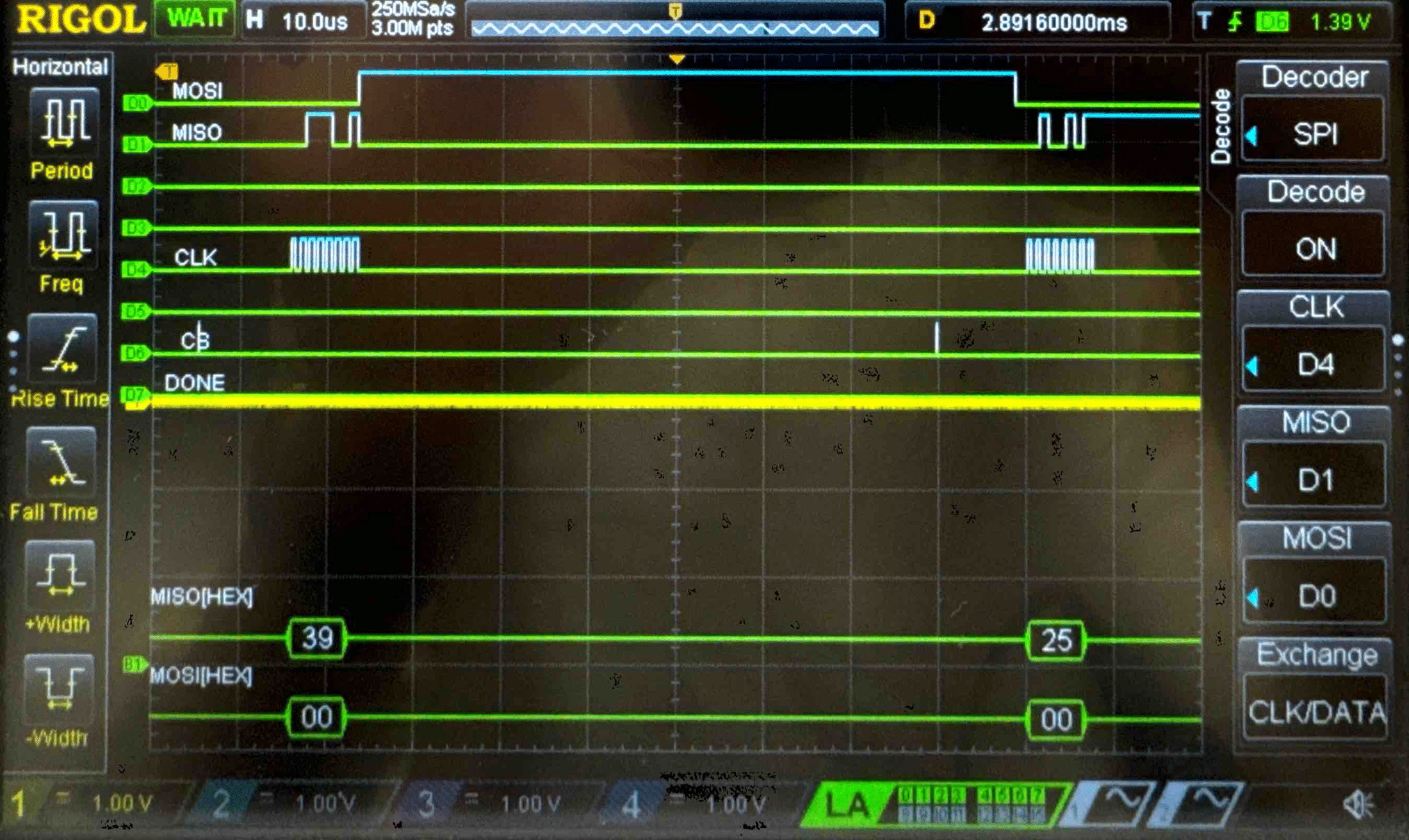
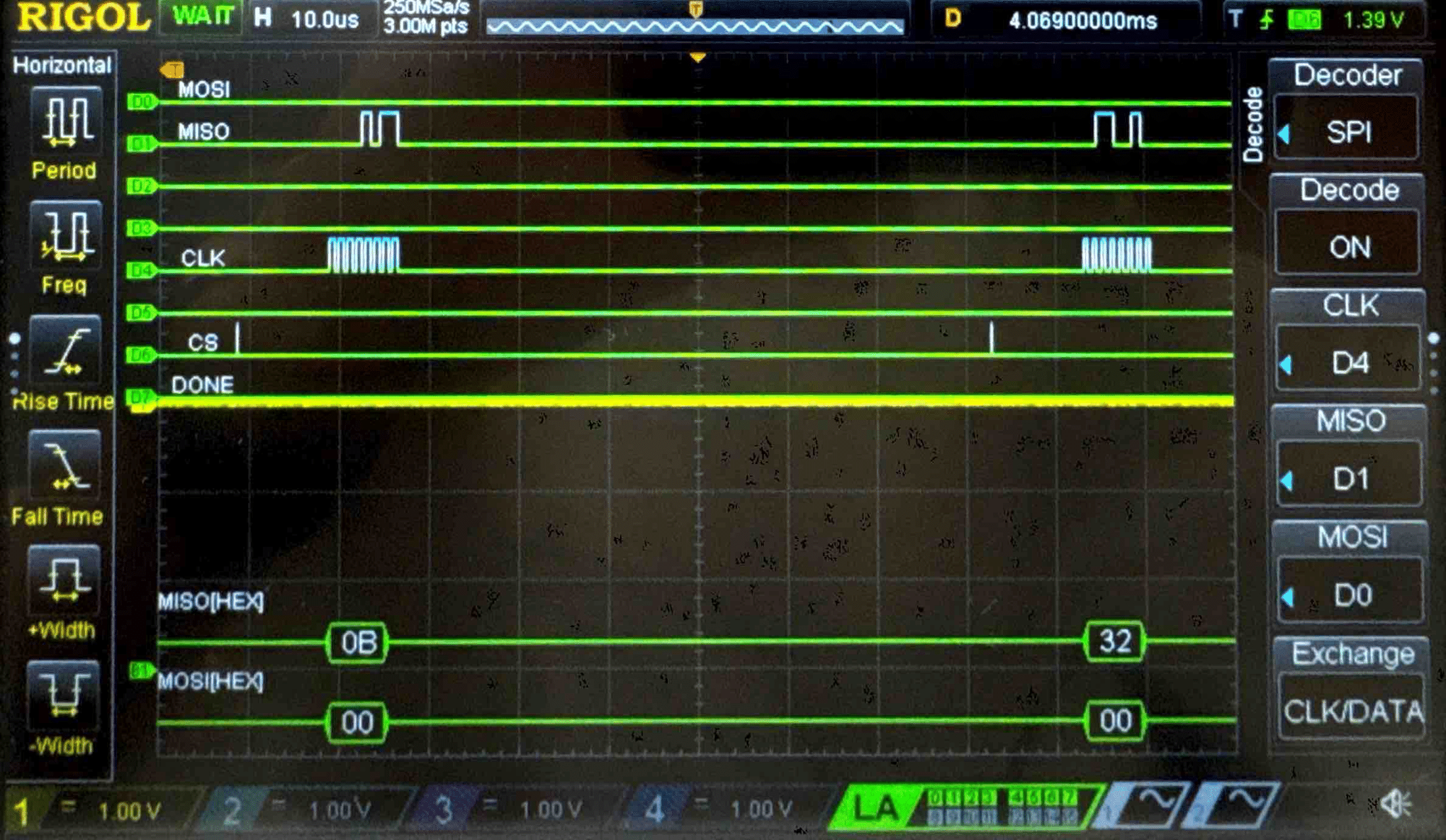
Cipher Text - Logic Analyzer Trace
AI Prototype
This week I prompted ChatGPT with “Write SystemVerilog HDL to implement the KeyExpansion logic described in the FIPS-197 uploaded document. The module should be purely combinational, using the previous key and current round number to calculate the next key. Assume other required modules (SubWord and RotWord) are already implemented.” For additional context, I provided the NIST AES Specifications.
// aes_keyexp_round.sv
// Combinational per-round AES-128 KeyExpansion
// Assumes SUBWORD and ROTWORD are provided elsewhere.
// Produces next 128-bit round key from previous 128-bit round key and round number.
//
// Reference: FIPS-197 Algorithm 2 (KEYEXPANSION) and Table 5 (Rcon).

module aes_keyexp_round #(
    parameter int AES_NK = 4   // only AES_NK==4 (AES-128) is implemented here
) (
    input  logic [127:0] prev_key,   // previous round key: {w0, w1, w2, w3} (big-endian word order)
    input  logic [3:0]   round_idx,  // round index (1..10 for AES-128). round_idx==0 -> next_key = prev_key (default)
    output logic [127:0] next_key
);

    // Rcon table (words): index 1..10 valid for AES-128
    localparam logic [31:0] RCON [1:10] = '{
        32'h01000000, 32'h02000000, 32'h04000000, 32'h08000000,
        32'h10000000, 32'h20000000, 32'h40000000, 32'h80000000,
        32'h1b000000, 32'h36000000
    };

    // Word extraction (big-endian grouping)
    logic [31:0] w0, w1, w2, w3;
    assign {w0, w1, w2, w3} = prev_key; // prev_key[127:96] = w0, [95:64]=w1, [63:32]=w2, [31:0]=w3

    // External helpers (assumed implemented elsewhere).
    // Provide prototypes so synthesis/simulation tools know the calls exist.
    // Replace these with module/task calls if your implementation exposes them differently.
    function automatic logic [31:0] SUBWORD(input logic [31:0] in_word);
        // implemented elsewhere; prototype only
    endfunction

    function automatic logic [31:0] ROTWORD(input logic [31:0] in_word);
        // implemented elsewhere; prototype only
    endfunction

    // Internal temps / outputs
    logic [31:0] temp, nw0, nw1, nw2, nw3;

    // Combinational expansion logic (AES-128/Nk==4)
    always_comb begin
        // Default: pass-through if round_idx == 0
        if (AES_NK != 4) begin
            // Not implemented for Nk != 4 in this module.
            // Output zeros to make behavior deterministic; caller should not use this for Nk != 4.
            next_key = '0;
        end else if (round_idx == 0) begin
            next_key = prev_key;
        end else begin
            // temp = SUBWORD(ROTWORD(w3)) XOR Rcon[round_idx]
            // round_idx range check: clamp 1..10 for AES-128
            int rindex = (round_idx < 1) ? 1 : (round_idx > 10) ? 10 : round_idx;
            temp = SUBWORD(ROTWORD(w3)) ^ RCON[rindex];

            // w4 = w0 ^ temp
            nw0 = w0 ^ temp;
            // w5 = w1 ^ w4
            nw1 = w1 ^ nw0;
            // w6 = w2 ^ w5
            nw2 = w2 ^ nw1;
            // w7 = w3 ^ w6
            nw3 = w3 ^ nw2;

            next_key = {nw0, nw1, nw2, nw3};
        end
    end
endmodule
The AI did pretty bad this week. The logic and sequence makes sense, however, it already is far too big to upload to our Upduino FPGA, likely because of the 96 XOR operations happening in parallel and the large functions it is declaring.
We can continue and see how the same LLM will perform for the same task with a new prompt: “Write SystemVerilog HDL to implement the following logic:
i = 0
while i < Nk do
    w[i] <- key[4*i..4*i+3]
    i <- i+1
end while
while i <= 4 * Nr + 3 do
    temp <- w[i-1]
    if i mod Nk = 0 then
        temp <- module1(module2(temp)) (+) Rcon[i/Nk]
    else if Nk > 6 and i mod Nk = 4 then
        temp <- module1(temp)
    end if
    w[i] <- w[i-Nk] (+) temp
    i <- i + 1
end while
return w
Assume module1 and module2 are existing modules that can be instantiated. (+) refers to XOR. Unwrap the loop in the provided pseudo code so it uses the previous iterations output to generate the new iteration.
Do not use any existing knowledge of the AES specifications in your answer.”
It produces the following:
module KeyExpansion #(
    parameter int Nk = 4,              // number of key words
    parameter int Nr = 10              // number of rounds
)(
    input  logic [32*Nk-1:0] key,      // input key (Nk words)
    input  logic [31:0]       Rcon   [0:((4*Nr+3)/Nk)],
    output logic [32*(4*Nr+4)-1:0] w   // expanded key words
);

    // Intermediate array of words
    logic [31:0] w_array [0:(4*Nr+3)];
    logic [31:0] temp;
    logic [31:0] mod1_out, mod2_out;

    // Modules (instantiated once, used combinationally)
    module1 u_mod1 (.in(temp), .out(mod1_out));
    module2 u_mod2 (.in(temp), .out(mod2_out));

    // Initial Nk words come directly from key
    genvar i;
    generate
        for (i = 0; i < Nk; i++) begin
            assign w_array[i] = key[32*i +: 32];
        end
    endgenerate

    // Iteratively expand key schedule
    always_comb begin
        for (int j = Nk; j <= 4*Nr + 3; j++) begin
            temp = w_array[j-1];
            if ((j % Nk) == 0) begin
                temp = mod1_out ^ Rcon[j/Nk];
            end
            else if ((Nk > 6) && ((j % Nk) == 4)) begin
                temp = mod1_out;
            end
            w_array[j] = w_array[j-Nk] ^ temp;
        end
    end

    // Flatten w_array to output vector
    generate
        for (i = 0; i <= 4*Nr + 3; i++) begin
            assign w[32*i +: 32] = w_array[i];
        end
    endgenerate
endmodule
Similarily to last time, this module is extremely expensive. ChatGPT is mindlessly running a lot of for loops many times more than necessary creating a lot fo extra hardware.
Conclusion
The design worked as intended. Our top level testbench passes with no errors and successfully returns the decrypted word.